
Solar photovoltaic panel monitoring device

A technology of solar photovoltaic panels and monitoring devices, applied in the monitoring of photovoltaic systems, photovoltaic modules, photovoltaic power generation, etc., can solve the problems of reduced power generation efficiency, high cost, and reduced solar power generation capacity, etc. The effect of low cost and reduced profit loss

Active Publication Date: 2016-11-16
STATE GRID CORP OF CHINA +1
View PDF5 Cites 3 Cited by
  • Summary
  • Abstract
  • Description
  • Claims
  • Application Information

AI Technical Summary

Problems solved by technology

[0002] The distributed solar photovoltaic panels currently used generally do not have an indication function. When a single solar photovoltaic panel fails, it is impossible to know whether the solar photovoltaic panel is working normally through existing means
For large-scale solar power generation devices that are arranged in a centralized manner, because the capacity of a single group is too small compared to the grid-connected capacity, it is generally impossible to carry out effective monitoring through telemetry data
Small or micro-scale distributed solar photovoltaics, because the installation site is generally at the top of the building, regular on-site measurement to check the working status of each solar photovoltaic panel, high cost and high safety risk
[0003] Since it is impossible to understand the working status of each solar photovoltaic panel, when individual solar photovoltaic panel components are not working normally, the solar power generation capacity of the entire group where they are located will be greatly reduced, which not only reduces the power generation efficiency, but also affects the three-phase unbalanced output. Stable operation of the inverter
In order to repair or find abnormal solar photovoltaic panel components, it can only be measured by a multimeter, which is time-consuming, laborious, inefficient, and poses safety risks for climbing operations

Method used


Image

  • Solar photovoltaic panel monitoring device
  • Solar photovoltaic panel monitoring device
  • Solar photovoltaic panel monitoring device

Examples


Embodiment Construction

[0019] It should be noted that, in the case of no conflict, the embodiments in the present application and the features in the embodiments can be combined with each other. The present invention will be described in detail below with reference to the accompanying drawings and examples.

[0020] Figure 1 to Figure 5 Some embodiments according to the invention are shown.

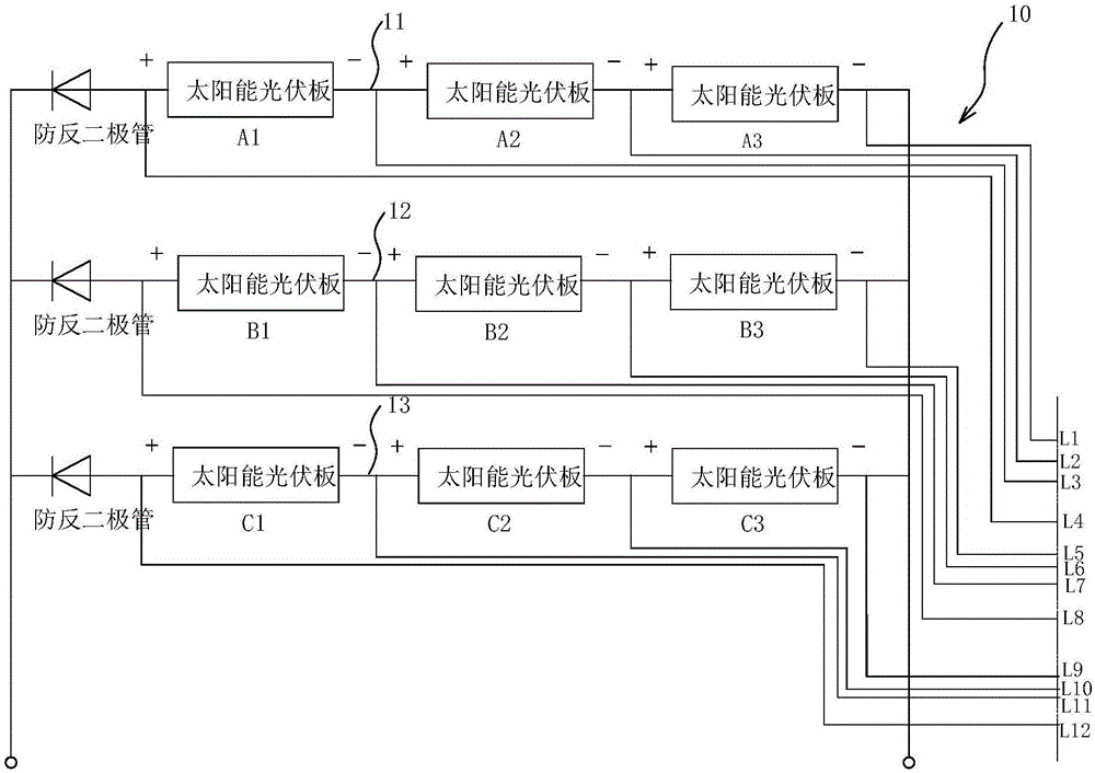
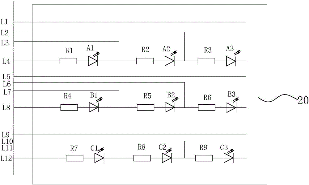
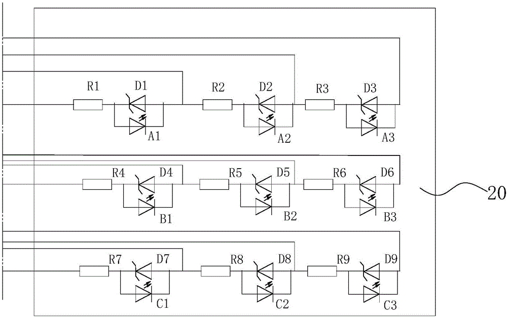
[0021] Such as figure 1 with figure 2 As shown, the solar photovoltaic panel monitoring device is used to monitor the monitoring object 10. The monitoring object 10 includes three power generation branches 11, 12, and 13 connected in parallel. An anti-reverse diode and multiple solar photovoltaic panels are connected in series on each power generation branch. , also includes a monitoring board 20, wherein, the monitoring board 20 is arrayed with a plurality of light-emitting diodes, wherein a plurality of solar photovoltaic panels on each power generation branch correspond to one row or column of light-emi...


PUM


Abstract

The invention discloses a solar photovoltaic panel monitoring device, which comprises a plurality of parallel generating branches. Each generating branch is connected in series with a plurality of solar photovoltaic panels and an anti-reverse diode. The solar photovoltaic panel monitoring device also comprises a monitoring plate, wherein a plurality of light-emitting diodes are arrayed on the monitoring plate. The plurality of solar photovoltaic panels of each generating branch are in one-to-one correspondence with one line or one row of light-emitting diodes on the monitoring plate; and each light-emitting diode is connected in series with a current-limiting resistor, and is connected in parallel with a solar photovoltaic panel in the corresponding position through a wire. The solar photovoltaic panel monitoring device is low in production cost, can visually display whether each group(piece) of solar photovoltaic panel is in a normal work state, and can quickly and timely find the relative positions of the group(piece) where the abnormally-working solar photovoltaic panels locate, thereby improving discovery and maintenance efficiency and reducing benefit loss.

Description

technical field [0001] The invention relates to a solar photovoltaic panel monitoring device. Background technique [0002] The distributed solar photovoltaic panels currently used generally do not have an indication function. When a single solar photovoltaic panel fails, it is impossible to know whether the solar photovoltaic panel is working normally through existing means. For centralized large-scale solar power generation installations, because the capacity of a single group is too small compared to the grid-connected capacity, it is generally impossible to carry out effective monitoring through telemetry data. Small or micro-scale distributed solar photovoltaic, because its installation location is generally on the top of the building, regular on-site measurement to check the working status of each solar photovoltaic panel, the cost is high, and the safety risk is great. [0003] Since it is impossible to understand the working status of each solar photovoltaic panel, ...

Claims


Application Information

Patent Timeline
Patent Type & Authority Applications(China)
IPC IPC(8): H02S50/10H02S50/15H02S40/30
CPCH02S40/30H02S50/10H02S50/15Y02E10/50
Inventor 宋驰李磊张浩李时孙静汪辉杜露露程小虎鲁晓威杨学梅潘金月姚治
Owner STATE GRID CORP OF CHINA
Learn More