


Quick Research
Generate reliable direction feasibility study reports for your R&D in just a few steps.

Technical Q&A
Discover and master advanced knowledge NOW. Basics, ideas, possibilities, all at once.

Find Solutions
As an expert in R&D theories, this can generate solutions to your technical problems instantly.

Evaluate Feasibility
Analyze your overall solution with one click, know your potential R&D risks in advance.

Monitor Landscape
Get weekly tech updates, stay abreast of the latest tech innovations and key insights.
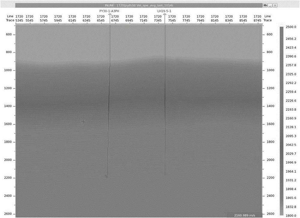
Fine velocity modeling method based on gas cloud region constraints
A velocity modeling and velocity model technology, applied in seismology, instruments, measuring devices, etc., can solve the problem of large spatial variation of velocity, failure to reflect the spatial variation relationship of velocity in gas cloud area and non-gas cloud area, and slow change of stratum lateral velocity and other problems, to achieve the effect of high time-depth conversion precision, improve application efficiency and logic
- Summary
- Abstract
- Description
- Claims
- Application Information
AI Technical Summary
Problems solved by technology
Method used
Image


Examples
Embodiment Construction
[0041] In order to have a clearer understanding of the technical features, purposes and effects of the present invention, the specific implementation manners of the present invention will now be described in detail with reference to the accompanying drawings.
[0042] Such as Figure 1-5 As shown, the first embodiment of the fine velocity modeling method based on gas cloud area constraints of the present invention.
[0043] Such as figure 1 As shown, the present embodiment is based on the fine velocity modeling method under the constraint of the gas cloud area and includes the following steps:
[0044] S1: Define the velocity model. The velocity model is a regular three-dimensional data grid. Each dimension has a fixed number of data, which respectively represent the number of main survey lines, the number of contact survey lines and the number of sampling points. Defining the velocity model is to set each The number of dimensions of data to meet the needs of actual work.
...
PUM
 Abstract
Description
Claims
Application Information
 - R&D Engineer
- R&D Manager
- IP Professional
- Industry Leading Data Capabilities
- Powerful AI technology
- Patent DNA Extraction
Browse by: Latest US Patents, China's latest patents, Technical Efficacy Thesaurus, Application Domain, Technology Topic, Popular Technical Reports.
© 2024 PatSnap. All rights reserved.Legal|Privacy policy|Modern Slavery Act Transparency Statement|Sitemap|About US| Contact US: help@patsnap.com