
A deflector device for high temperature gas

A deflector and high-temperature technology, applied in combustion chambers, combustion methods, combustion equipment, etc., can solve the problems of reducing the service life of gas deflectors, reducing the combat effectiveness of aircraft carriers, and increasing maintenance costs of aircraft carriers, so as to improve the atomization effect , Improve the cooling effect and reduce the impact effect

Active Publication Date: 2019-04-23
SOUTHEAST UNIV
View PDF4 Cites 4 Cited by
  • Summary
  • Abstract
  • Description
  • Claims
  • Application Information

AI Technical Summary

Problems solved by technology

At present, there are two main cooling methods used by the gas deflector. One is mainly relying on the heat conduction of metal materials, but due to the limitation of the heat conduction capacity of the material itself, it is often impossible to dissipate heat in time, which makes the plate often in a high temperature state. It is very easy to burn, which greatly reduces the service life of the gas deflector, increases the maintenance cost of the aircraft carrier, and reduces the combat effectiveness of the aircraft carrier; another cooling method is liquid cooling, which is cooled by a number of seawater installed on the lower surface Cooling is achieved by pipe convection heat exchange to achieve the safe working temperature range of the gas deflector, and the cooling water temperature is controlled not to exceed 100°C by adjusting the flow of cooling sea water
But even with forced convection, the convective heat transfer coefficient of seawater is only 1000~1500W / m 2. K

Method used


Image

  • A deflector device for high temperature gas
  • A deflector device for high temperature gas
  • A deflector device for high temperature gas

Examples


Embodiment Construction

[0028] Carry out the description of specific implementation below in conjunction with accompanying drawing:

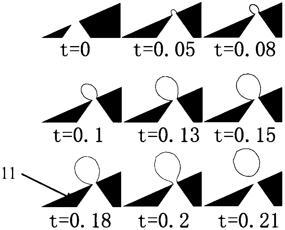
[0029] figure 1 The situation where the liquid is heated and boiled on one of the teeth of the saw-toothed base 11 to generate bubbles is simulated, and the gasification core is given during the simulation.

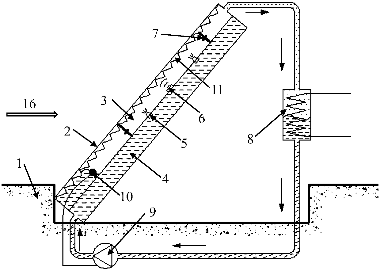
[0030] image 3 A schematic diagram of the gas deflector device for efficiently dissipating heat by using phase change is given, which is mainly composed of two parts: the deflector and the external circulation heat exchange system. When the deflector plate body 2 does not need to work, it is directly embedded in the deck 1, which can save space. The deflector includes a deflector plate body 2 , a phase change atomization chamber 3 and a liquid chamber 4 , and the inner surface of the deflector plate body 2 is a serrated base 11 . The external circulation heat exchange system includes a heat exchanger 8 , a pump 9 and a plate liquid level control device 10 . T...


PUM


Abstract

The invention discloses a guide plate device used for high-temperature fuel gas. The guide plate device comprises a guide plate and an outer circulation heat exchange system. The guide plate comprises a guide plate body, an atomization phase change chamber and a liquid chamber. The atomization phase change chamber is located between the guide plate body and the liquid chamber. The liquid chamber is provided with a nozzle and an ultrasonic generator, wherein the nozzle sprays liquid in the liquid chamber out and conducts primary atomization in the atomization phase change chamber, and the ultrasonic generator is used for conducting secondary atomization on liquid drops obtained after primary atomization. The atomization phase change chamber is used for gasifying the atomized liquid drops under the condition that the guide plate body is subjected to the effect of the high temperature. The outer circulation heat exchange system comprises a heat exchanger and a liquid conveying pump. A gas inlet of the heat exchanger is connected with a gas outlet, and a cooling water outlet of the heat exchanger is connected with the liquid chamber through the liquid conveying pump. Compared with the prior art, the change processes that liquid is atomized into the liquid drops and the liquid drops absorb heat to be gasified are utilized, the fuel gas guide plate is rapidly and continuously cooled.

Description

technical field [0001] The invention relates to a gas deflector, in particular to a gas deflector which uses boiling phase change heat transfer technology to efficiently dissipate heat. Background technique [0002] my country is a large country with nearly 3 million square kilometers of oceanic territory. How to maintain our country's territorial waters and maritime rights and interests has become an urgent problem for us to solve. Aircraft carriers, as an indispensable weapon for the modern navy to seize large-scale sea and air control, have important strategic significance for my country's coastal defense. Fighter planes are one of the important combat weapons of aircraft carriers. In recent decades, with the gradual improvement of combat requirements, fighter planes carry more and more weapons, their take-off weights are getting heavier, and their required take-off speeds are also increasing. High, a take-off method that can make fighter jets reach the required take-off...

Claims


Application Information

Patent Timeline
Patent Type & Authority Patents(China)
IPC IPC(8): F23R3/28
CPCF23R3/28
Inventor 张程宾杨飞戴俏波陈永平
Owner SOUTHEAST UNIV
Learn More