Wing connecting device, wing and aircraft

A connecting device and wing technology, which is applied in the direction of wings, aircraft parts, transportation and packaging, etc., can solve the problems of low safety of wing connecting device, damage of wing connecting device, wing falling off, etc., so as to reduce assembly errors Rate and scrap rate, reduced calibration steps, improved safety effects

Active Publication Date: 2018-06-15
青州耐威智能科技有限公司
View PDF7 Cites 0 Cited by
  • Summary
  • Abstract
  • Description
  • Claims
  • Application Information

AI Technical Summary

Problems solved by technology

[0004] Therefore, the technical problem to be solved by the embodiment of the present invention is that the wing connection device in the prior art will be damaged when the stall is recovered, and the wing will fall off when it is subjected to a large load, etc. The wing connection device in the prior art has low safety and durability. Low

Method used


Image

  • Wing connecting device, wing and aircraft
  • Wing connecting device, wing and aircraft
  • Wing connecting device, wing and aircraft

Examples


Embodiment 1

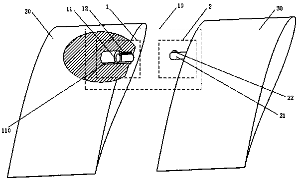
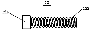
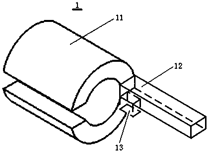
[0038] This embodiment provides a wing connection device, which can be applied to the assembly of aircraft wings, such as the assembly of the inner and outer wings of a fixed-wing unmanned aerial vehicle, such as figure 1 As shown, the wing connection device 10 includes: a first joint unit 1 and a second joint unit 2 . The first joining unit 1 is embedded in the first wing part 20 , and the first wing part 20 may be, for example, an inner wing or an outer wing. The first joining unit 1 includes a hollow rotating column 11 and a telescopic block 12 . Rotary column 11 is used for rotating around its axis, as figure 1 As shown, the rotating column 11 is in the shape of a hollow cylinder, and the rotating column 11 may also be a hollow cone, a truncated cone, a cuboid, etc. according to actual needs. The cylindrical rotating column 11 has side surfaces and two bottom surfaces, and the rotating column 11 can rotate around its central axis. A groove 110 parallel to the axis of th...

Embodiment 2

[0045] This embodiment provides a wing connecting device, such as Figure 4 As shown, in addition to the features of the wing connection device in Embodiment 1, it also includes: a first positioning hole 3 and a first positioning pin 4 . The first positioning hole 3 is embedded in the first wing portion 20 . The first positioning pin 4 is circumscribed on the second wing portion 30 , and is used for cooperating with the first positioning hole 3 to be inserted into the first positioning hole 3 .

[0046] The effect of the first positioning hole 3 and the first positioning pin 4 is mainly to assist positioning when the first and second wing parts are docked, and further ensure that the outer surfaces of the first wing part 20 and the second wing part 30 are in the same shape. Cooperate. Moreover, the cooperation between the first positioning hole 3 and the first positioning pin 4 can also prevent the relative rotation of the first and second wing parts during flight, thereby i...

Embodiment 3

[0054] This embodiment provides a wing, including: a first wing part 20 , a second wing part 30 , and the wing connection device 10 of the above-mentioned embodiment 1 or 2. The first wing part 20 is connected to the second wing part 30 through the wing connecting device 10 . The wing has the advantages of high safety and high durability.


PUM


Abstract

The invention discloses a wing connecting device, a wing and a plane, and belongs to the technical field of plane installation. The wing connecting device comprises a first connecting unit and a second connecting unit, wherein the first connecting unit is embedded in a first wing portion and comprises a hollow rotary pillar and an extensible block; the rotary pillar is used for rotating around the axis of the rotary pillar; a groove parallel to the axis of the rotary pillar is formed in the lateral surface of the rotary pillar; a fixed end of the extensible block is connected with the first wing portion, and an extensible end of the extensible block is connected with one side bottom surface of the rotary pillar or located in the groove; the second connecting unit is located at a second wing portion in an external connecting mode and used for being matched with the first connecting unit so that the first wing portion and the second wing portion can be connected and comprises a rod capable of being inserted into the hollow structure of the rotary pillar and a protruding block capable of being inserted into the groove; one end of the rod is connected with the second wing portion; and the protruding block is connected to a position located on the rod and near the other end of the rod. The wing connecting device, the wing and the plane have the advantages of being high in safety and high in durability.

Description

technical field [0001] The invention relates to the technical field of aircraft installation, in particular to a wing connection device, a wing and an aircraft. Background technique [0002] At present, most aircraft are completed through assembly. For example, unmanned aerial vehicle is a typical type of aircraft completed through assembly. It is a new industry with broad market prospects. In order to save space, fixed-wing UAVs are usually assembled by dividing the wings into several parts. The most common method of division is to divide the wings into one section of inner wing and two sections of outer wing. [0003] The methods of assembling between the inner and outer wings are also different. One of the commonly used methods is plugging, for example, inserting the rod on the outer wing into the hole on the inner wing, and then locking the rod with a lock. This method has a disadvantage. When the UAV stalls and recovers, the fuselage will collide violently with the gro...

Claims


Application Information

Patent Timeline
Patent Type & Authority Patents(China)
IPC IPC(8): B64C3/00
CPCB64C3/00
Inventor 王凯赛陈明军张昆曹立金
Owner 青州耐威智能科技有限公司
Why Eureka
Try Eureka