
Handheld type composite ultrasonic food splitting tool

An ultrasonic and hand-held technology, applied in the field of hand-held composite ultrasonic food slitting and cutting knives, can solve the problems of difficult operation, difficult cutting of food, and low cutting efficiency, so as to achieve smooth and flat cutting surface, saving manpower and raw material costs, and cutting efficiency Improved effect

Pending Publication Date: 2016-11-16
CHEERSONIC ULTRASONICS CO LTD
View PDF0 Cites 0 Cited by
  • Summary
  • Abstract
  • Description
  • Claims
  • Application Information

AI Technical Summary

Problems solved by technology

The existing ultrasonic food cutting system is widely used in the market due to its advantages of smooth cutting surface and non-stick raw materials. However, due to its bulky size and difficult operation, it can only be applied to large-scale production and assembly line production
Since the traditional ultrasonic food cutting equipment only has longitudinal reciprocating motion, the food is not easy to cut, the cut surface is uneven, and the cutting efficiency is low during the hand-held cutting process. Based on the adjustment of the ultrasonic food cutting knife, without changing the stability of the ultrasonic wave, the applicant of the patent researched and developed a hand-held composite ultrasonic food cutting tool with transverse and longitudinal vibration, high cutting efficiency and small size Knife

Method used


Image

  • Handheld type composite ultrasonic food splitting tool
  • Handheld type composite ultrasonic food splitting tool
  • Handheld type composite ultrasonic food splitting tool

Examples


Embodiment Construction

[0009] Specific embodiments of the present invention will be described in detail below in conjunction with the accompanying drawings.

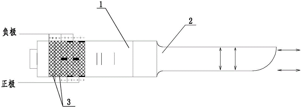
[0010] Such as Figure 1-Figure 3 As shown, the present invention includes an ultrasonic transducer 1 with four piezoelectric ceramics and a titanium alloy cutter 2, each piezoelectric ceramic is an integral structure, and the titanium alloy cutter 2 is fixedly arranged on the ultrasonic transducer 1 through screw fit. Under the action of the drive power supply, the piezoelectric ceramics reciprocate longitudinally, thereby converting electrical energy into mechanical energy; the hand-held composite ultrasonic food cutting knife also includes two piezoelectric ceramics 3, two piezoelectric ceramics 3 are respectively symmetrical split structures and are arranged oppositely. Two piezoelectric ceramics 3 are arranged at the rear end of four piezoelectric ceramics, and the positive and negative poles of the two piezoelectric ceramics 3 and the ad...


PUM


Abstract

The invention provides a handheld type composite ultrasonic food splitting tool and belongs to the technical field of ultrasonic cutting of food. The handheld type composite ultrasonic food splitting tool comprises an ultrasonic transducer with four piezoelectric ceramics and a titanium alloy cutter, each piezoelectric ceramic is of an integrated structure, and the titanium alloy cutter is arranged at the front end of the ultrasonic transducer. The handheld type composite ultrasonic food splitting tool further comprises two piezoelectric ceramics, each of the two piezoelectric ceramics is of a symmetrical split type structure and arranged in an opposite manner, and the two piezoelectric ceramics are arranged behind the four piezoelectric ceramics. The positive electrodes and negative electrodes of the two piezoelectric ceramics and the positive electrode and the negative electrode of the piezoelectric ceramic adjacent to the two piezoelectric ceramics are arranged in a staggered manner, the positive electrodes and the negative electrodes of the rest of piezoelectric ceramics are consistently placed, the two piezoelectric ceramics do transverse reciprocating motion under the action of a drive power source, the front ends and the rear ends of the six piezoelectric ceramics are correspondingly supported through a front end cover and a rear end cover in a cover mounting manner, and a handle is fixedly arranged at the rear end of the ultrasonic transducer in a threaded fit manner.

Description

technical field [0001] The invention belongs to the technical field of food ultrasonic cutting, and in particular relates to a hand-held composite ultrasonic food cutting knife. Background technique [0002] Food cutting machinery is an emerging industry. With the improvement of people's living standards, the requirements for food are increasing year by year, and the requirements for food quality and hygiene are becoming stronger and stronger. Over the years, food cutting machinery has not only scaled up, but is also moving towards full automation, and products with high technical content are constantly emerging. The existing ultrasonic food cutting system is widely used in the market due to its advantages of smooth cutting surface and non-stick raw materials. However, due to its bulky size and difficult operation, it can only be applied to large-scale production and assembly line production. Since the traditional ultrasonic food cutting equipment only has longitudinal reci...

Claims


Application Information

Patent Timeline
IPC IPC(8): B26B3/00
CPCB26B3/00
Inventor 李捷飞
Owner CHEERSONIC ULTRASONICS CO LTD
Learn More