
Workpiece clamping device

A workpiece clamping and frame technology, which is applied in the direction of clamping devices, positioning devices, metal processing machinery parts, etc., can solve the problems of poor clamping effect of workpieces, complex structure of clamping devices, high cost, etc., and achieve good clamping effect , good support and anti-loosening, low cost effect

Inactive Publication Date: 2016-11-16
桐乡守敬应用技术研究院有限公司
View PDF5 Cites 7 Cited by
  • Summary
  • Abstract
  • Description
  • Claims
  • Application Information

AI Technical Summary

Problems solved by technology

Common workpieces are generally only clamped on the upper surface of the workpiece during processing, but during processing, the clamping effect of the workpiece is not good, and it will move during the processing
Moreover, the current common clamping device has a relatively complicated structure and high cost.

Method used


Image

  • Workpiece clamping device
  • Workpiece clamping device

Examples


Embodiment Construction

[0012] The present invention will be further described in detail below in conjunction with the accompanying drawings and examples. The following examples are explanations of the present invention and the present invention is not limited to the following examples.

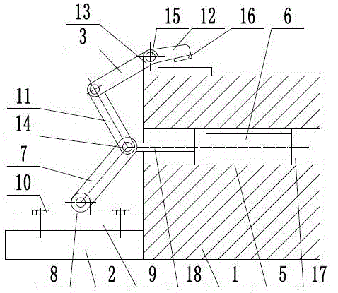
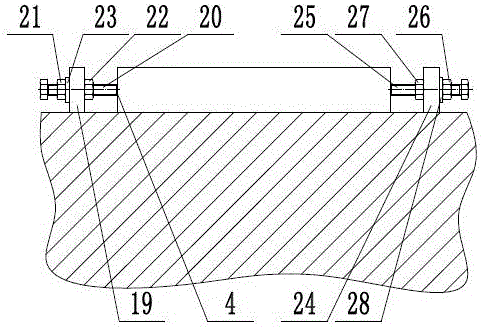
[0013] Such as figure 1 with figure 2 As shown, a workpiece clamping device includes a frame 1, a side support 2, a clamping assembly 3, and a limit assembly 4. The frame 1 is provided with a horizontal support groove 5, and the side support 2. Fixed on one side of the frame 1, the clamping assembly 3 includes a driving cylinder 6, a rocker 7, a rocker support seat 8, a support plate 9, a fastening screw 10, a connecting rod 11, a curved pressure plate 12, and a pressure plate Support base 13, first pin shaft 14, second pin shaft 15, pressure pad 16, the support plate 9 is installed on the side support 2 through fastening screws 10, and the rocker support base 8 is fixed on the support plate 9 Above, the lower en...


PUM


Abstract

The invention provides a workpiece clamping device, and belongs to the technical field of machining. The workpiece clamping device comprises a clamping assembly and a limiting assembly. The lower end of a rocker of the clamping assembly is hinged to a rocker supporting base, and the upper end of the rocker and the lower end of a connecting rod are hinged through a first hinge pin. A bent press plate is hinged to a press plate supporting base through a second hinge pin, one end of the bent press plate and the upper end of the connecting rod are hinged, and a press cushion is arranged on the lower side of the other end of the bent press plate. One end of a piston rod of a driving cylinder and the first hinge pin are hinged. A left supporting plate and a right supporting plate of the limiting assembly are symmetrically arranged on the two sides of a machine frame. A left stop screw penetrates through the left supporting plate, and a first supporting nut and a first locking nut are in threaded connection with the left stop screw. A right stop screw penetrates through the right supporting plate, and a second supporting nut and a second locking nut are in threaded connection with the right stop screw. The workpiece clamping device has a good clamping effect on workpieces, effectively prevents the workpieces from moving in the machining process, and is reasonable in structure and low in cost.

Description

technical field [0001] The invention relates to the technical field of mechanical processing, in particular to a workpiece clamping device. Background technique [0002] Machining refers to the process of changing the shape or performance of a workpiece through a mechanical device. According to the difference in processing method, it can be divided into cutting processing and pressure processing. In the production process, the process of changing the shape, size, position and nature of the production object to make it a finished or semi-finished product is called a process. It is an essential part of the production process. The process can be divided into casting, forging, stamping, welding, machining, assembly and other processes. The mechanical manufacturing process generally refers to the sum of the machining process of parts and the assembly process of machines. Other processes are called auxiliary processes. Processes, such as transportation, storage, power supply, e...

Claims


Application Information

Patent Timeline
Patent Type & Authority Applications(China)
IPC IPC(8): B23Q3/08
CPCB23Q3/08B23Q2703/04
Inventor 邱洪波
Owner 桐乡守敬应用技术研究院有限公司
Learn More