
Hybrid power delivery system for an aircraft mover

A conveying system and hybrid power technology, applied in the field of hybrid power conveying systems for aircraft mobile machines, can solve the problems of reduced power transmission, waste of energy, increased cost of tractors, etc., and achieve fast power transmission and realize power transmission. Effect

Inactive Publication Date: 2016-11-09
TEXTRON GROUND SUPPORT EQUIP UK
View PDF0 Cites 3 Cited by
  • Summary
  • Abstract
  • Description
  • Claims
  • Application Information

AI Technical Summary

Problems solved by technology

[0004] Both solutions have disadvantages: a single aircraft tug with a large enough engine to power the largest aircraft will waste a lot of energy pulling lighter aircraft; conversely, using aircraft tugs of various sizes requires all higher initial outlay
Larger engines also require more maintenance than smaller engines, resulting in costly and time-consuming tractor repairs
[0007] Optimum practice would therefore be to provide a structure for powering the aircraft tug or mover where the initial power delivery is high, but once the initial resistance is overcome the power delivery is substantially reduced

Method used


Image

  • Hybrid power delivery system for an aircraft mover
  • Hybrid power delivery system for an aircraft mover
  • Hybrid power delivery system for an aircraft mover

Examples


Embodiment Construction

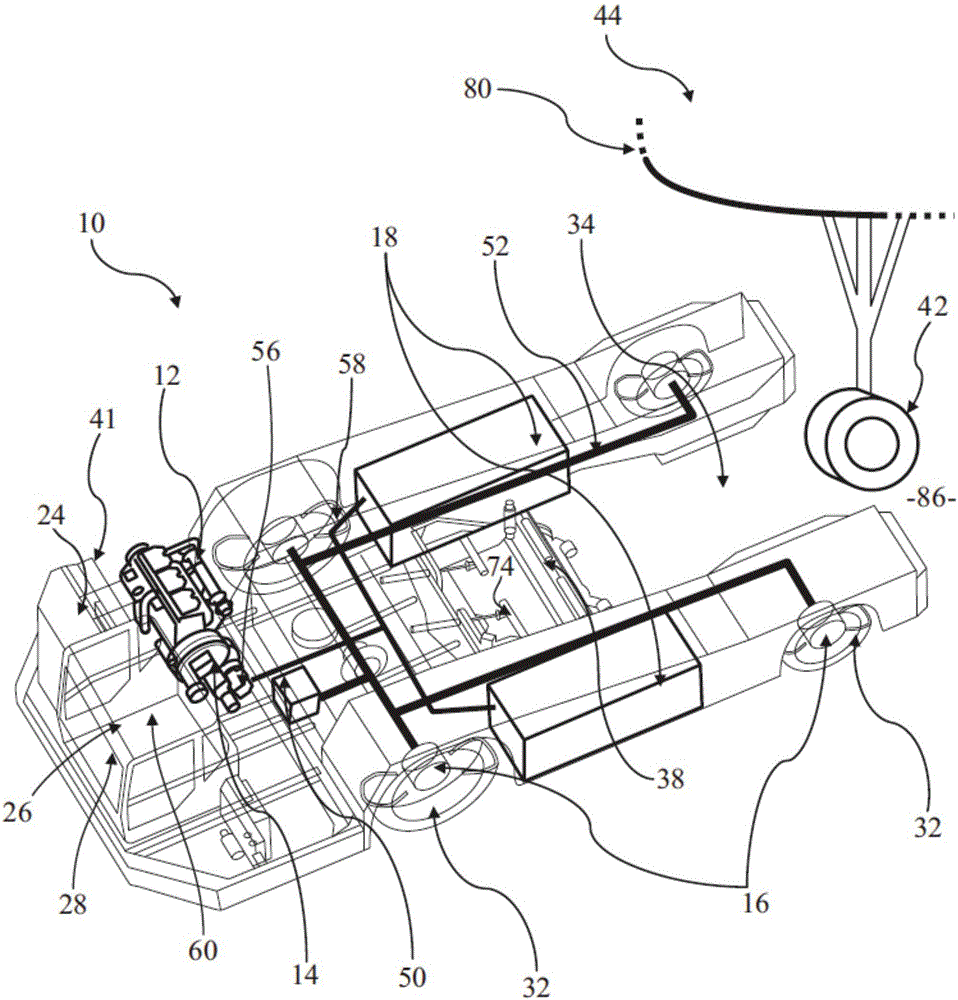
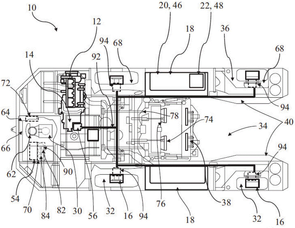
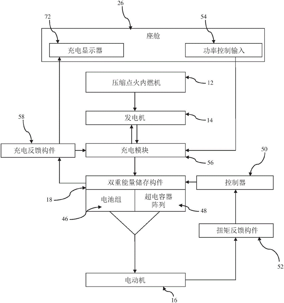
[0048] First refer to the diagram in the figure 1 with figure 2 , an aircraft tractor 10 is shown, which is an electric hybrid aircraft mobile vehicle having a compression-ignition internal combustion engine, in this case a diesel engine 12 , a generator 14 and at least one electric motor 16 . There is also provided a dual electrical energy storage and supply system 18 comprising a first electrical energy storage and supply means 20 and a second electrical energy storage and supply means 22 different from the first energy storage means 20 .

[0049] Aircraft tug 10 includes a chassis 24 , a cockpit 26 preferably located at a front end 28 of tug 10 (from which an operator 30 can control tug 10 ), a plurality of wheels 32 and an aircraft cockpit located at a rear 36 of tug 10 . Joint area 34 . Typically, aircraft tug 10 has four wheels 32 , although tugs or other types of aircraft movers with different numbers of wheels are contemplated.

[0050] Aircraft engagement area 34 ...


PUM


Abstract

There is provided a method of moving an aircraft using an aircraft mover (10), preferably an aircraft tractor. The method comprises the steps of: a] accelerating the aircraft up to speed using one or more electric motors (16) drivable by at least a fast-discharge electrical-energy storage and supply device (20) during a high-power requirement of the aircraft mover (10); b] substantially maintaining a speed of the aircraft using a slow-discharge electrical-energy storage and supply device (22) during a low-power requirement of the aircraft mover (10); c] monitoring a charge status of the slow-discharge and fast-discharge energy storage and supply devices (20, 22) and when a predetermined charge status is reached, automatically charging the slow-discharge and / or fast-discharge energy storage and supply devices (20, 22) via an onboard electricity generator (14); and d] regeneratively recharging the slow-discharge and / or fast-discharge electricity-energy storage and supply devices (20, 22) during at least deceleration of the aircraft coupled to the aircraft mover (10). There is also provided a method of controlling the power distribution to the motors (16) within the aircraft mover (10), a dual electrical-energy storage and supply system (18) and controller (50) for implementing said method, a hybrid power delivery system for an aircraft mover incorporating the dual electrical-energy storage and supply system and controller, and an aircraft mover (10) using said systems.

Description

technical field [0001] The present invention relates to a method of moving an aircraft using an aircraft moving machine, in particular but not necessarily exclusively an aircraft traction vehicle, and having a dual electrical energy storage and supply system. The present invention further relates to a method of controlling the distribution of power to an aircraft mobile machine, further to a hybrid power delivery system for an aircraft mobile machine, and further to a dual electrical energy storage and supply device and a method for controlling such electrical power mixing The control member of the power distribution of the aircraft mobile machine. Background technique [0002] Aircraft tugs or movers are heavy vehicles necessary to tow and / or maneuver all types of aircraft. In contemporary aircraft tractors there is usually a diesel compression ignition internal combustion engine with direct transmission to the drive axles or wheels. Therefore, the engine directly provide...

Claims


Application Information

Patent Timeline
IPC IPC(8): B60L11/02B60K7/00B64F1/22B60L50/10
CPCB60K7/0007B60L50/10B60L2200/36B64F1/225B60K6/28B60K6/46B60L1/003B60L7/14B60L15/2045B60L50/40B60L58/12B60L58/20B60L2200/40B60L2220/44B60L2240/423B60L2240/441B60L2260/28B60W10/26B60W20/19B64F1/227Y02T10/62Y02T10/64Y02T10/70Y02T10/72Y02T50/80Y02T90/16B60W20/00
Inventor 图沙尔·库尔卡尼保罗·钱农
Owner TEXTRON GROUND SUPPORT EQUIP UK
Learn More