
Mirror network flow control protocol in virtualization network environment

A flow control and mirroring network technology, applied in the field of information security, can solve the problems of resource waste, serious occupation of business physical computer computing resources and network resources, analysis of data packet occupation, etc.

Active Publication Date: 2016-11-09
BEIJING RUIHE YUNTU TECH CO LTD
View PDF4 Cites 41 Cited by
  • Summary
  • Abstract
  • Description
  • Claims
  • Application Information

AI Technical Summary

Problems solved by technology

[0005] The image diversion scheme that captures the data packets on the virtual switch through the security virtual machine and exports them to the specified network device has the following problems: 1) Computing resource problem: the security virtual machine needs to be deployed in the user's business environment In order to capture mirrored packets from the virtual switch
A certain amount of computing resources (IO and interrupts) have been occupied from data packet capture to export. If it is necessary to perform complex deep packet inspection on each data packet, it will greatly occupy the computing resources of the user's business environment, making the solution unacceptable
2) Network resource issues: In a real business environment, virtual machines are usually deployed on blade servers, which makes the traffic from the security virtual machine usually occupy the physical link of the business network. Exporting after any optimization will double the network bandwidth usage, and optimization means that more computing resources need to be analyzed for data packets
3) Deduplication of mirroring traffic: the communication traffic between virtual machines on two different physical devices will be captured by different security virtual machines, that is, one copy of traffic is captured twice, while the traffic between security virtual machines is not communicated. In this case, it is difficult to judge whether there is repeated traffic. At this time, all export will bring additional load pressure on network resources and security devices, and it is a waste of resources.
4) Multi-purpose diversion problem: Security detection and auditing are not just the work of one device of the intrusion detection system, but often require a variety of special detection and auditing devices to cooperate, such as network auditing, database auditing, intrusion detection, application performance management The system uses more and more devices such as situational awareness and data analysis based on big data
However, when the mirroring traffic of a virtual machine is guided from one physical machine to multiple physical devices at the same time, the work of copying data packets and exporting network flows will seriously occupy the computing resources and network resources of the business physical machine, which is almost Become a task that cannot be realized in the current stage of virtualized network environment
Moreover, different types of detection and audit equipment have different requirements for network traffic. For example, database audit only needs database access traffic, intrusion detection systems focus on in-depth data packet information, and situational awareness needs more basic information on network flows. 5) Scalability issues: the introduction of concepts such as agility and linkage makes network security needs to support more complex policies, implement security monitoring policies on demand, and modify security policies in real time through software definition, etc.
However, this architecture alone cannot constitute a complete and implementable solution. A mirror flow control protocol that can support this architecture is also required. Through this protocol, the software-defined and decoupled control and forwarding separation structures can be connected in series to be able to Constitute a complete and available mirror traffic monitoring and management solution

Method used


Image

  • Mirror network flow control protocol in virtualization network environment
  • Mirror network flow control protocol in virtualization network environment
  • Mirror network flow control protocol in virtualization network environment

Examples


Embodiment Construction

[0039] The present invention will be described in further detail below in conjunction with the accompanying drawings.

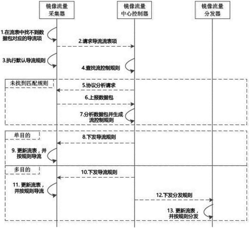
[0040] like Figure 10 As shown, assuming that the network load of physical host A is high, the communication traffic between virtual machine A and virtual machine B is not in the diversion flow tables of mirrored traffic collector 1 and mirrored traffic collector 2 . The communication traffic between virtual machine A and virtual machine B includes video service flow and internal calls of general business systems. The internal call traffic of the business system needs to be monitored and audited by the intrusion detection system and application performance management system, but the The flow entry also does not exist in the mirror traffic center controller. The reason is that the mirrored traffic center controller only stores policies issued by users through software definition instead of specific flow entries. Policy such as protocol X of virtual machine ...


PUM


Abstract

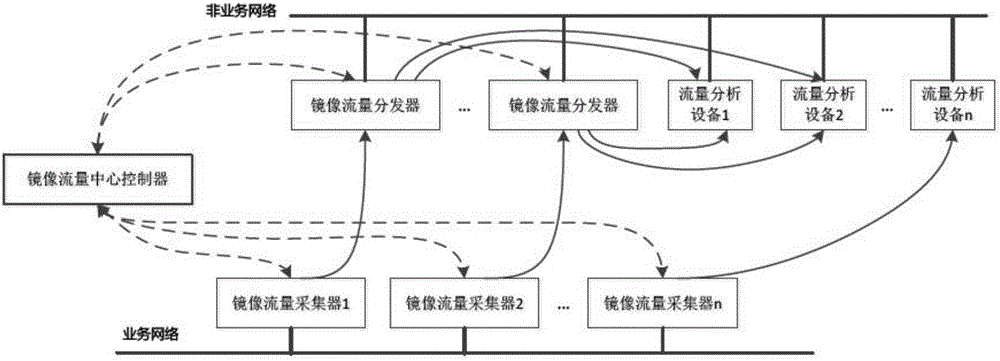
A mirror network flow control protocol based on a software definition in a virtual network environment is characterized in that the protocol can adapt a system structure of mirror flow collection, mirror flow distribution and mirror flow control, which is decoupling in functions and has distributed disposition. A mirror flow collector node / virtual machine is deployed in a business network environment of a user, and has a main function to capture the mirror flow in the virtual network environment and to carry out forwarding according to a target assigned by the protocol. A mirror flow dispatcher is deployed in a non-business network environment, that is the influence of a network load on the normal network communication of the user business network environment does not need to be considered, and the function of the mirror flow dispatcher is to carry out flow copy and distribution according to a multi-purpose flow analysis device assigned by the protocol. A mirror flow center controller uniformly controls forwarding logic of the whole mirror network flow, and provides soft defined interfaces.

Description

technical field [0001] The invention relates to the technical field of information security, in particular to a control scheme and a control protocol for mirrored network traffic in a virtualized network environment. Background technique [0002] In a virtualized network environment, the virtual network boundary is composed of virtual machines and isolation solutions such as VLAN or VXLAN, while the physical network boundary is still composed of traditional physical network switches and network links. This makes the virtual network boundary of a network composed of virtual machines inconsistent with the physical network boundary. When a traditional physical security device mirrors network traffic from the physical network boundary (uplink port of a physical switch), it cannot obtain the network traffic corresponding to a complete virtual network boundary. Virtual machines can communicate directly through virtual switches without forwarding traffic to physical network links,...

Claims


Application Information

Patent Timeline
IPC IPC(8): H04L12/741H04L12/803H04L12/931H04L29/06H04L29/08H04L45/74
CPCH04L45/54H04L47/125H04L49/354H04L63/1425H04L67/1095H04L67/1001
Inventor 不公告发明人
Owner BEIJING RUIHE YUNTU TECH CO LTD
Learn More