
Connecting ring and socket as well as pulling and separating connector

A technology of connecting rings and connectors, applied in the direction of connection, parts of connecting devices, electrical components, etc., can solve the problem that the plug and socket cannot be automatically disconnected smoothly, and achieve the effect of convenient use.

Active Publication Date: 2016-11-09
CHINA AVIATION OPTICAL-ELECTRICAL TECH CO LTD
View PDF5 Cites 5 Cited by
  • Summary
  • Abstract
  • Description
  • Claims
  • Application Information

AI Technical Summary

Problems solved by technology

[0004] However, this kind of pull-off connector only realizes the unlocking of the plug and socket after the pull cord pulls the connecting sleeve backward, and the plug and socket cannot be automatically disengaged smoothly in a special use environment, and the pull and pull of the design requirements cannot be met. The purpose of the rope can be automatically disengaged

Method used


Image

  • Connecting ring and socket as well as pulling and separating connector
  • Connecting ring and socket as well as pulling and separating connector
  • Connecting ring and socket as well as pulling and separating connector

Examples


Embodiment Construction

[0025] Embodiments of the present invention will be further described below in conjunction with the accompanying drawings.

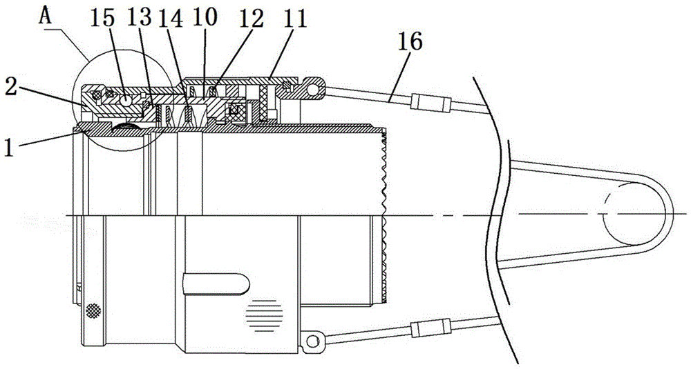
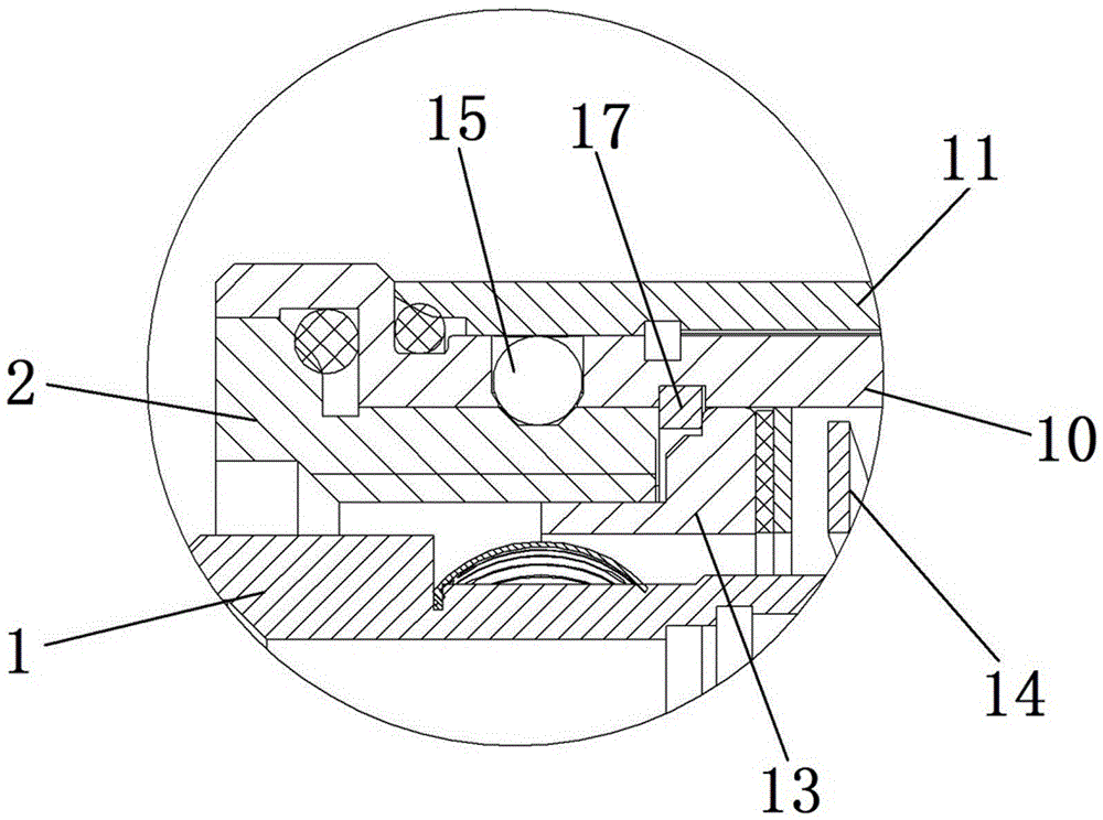
[0026] Specific embodiments of the pull-off connector of the present invention, such as Figure 1-2 As shown, a socket is included, and the socket includes a socket housing 1 , contacts are installed in the inner cavity of the socket housing 1 , and a connecting sleeve 10 is fixedly installed on the outside. Wherein, the connecting sleeve 10 of the socket is locked and connected with the connecting ring 2 through a steel ball locking structure.

[0027] The structure of connecting sleeve 10 is as Figure 5-6 As shown, the front part of the connecting sleeve 10 is provided with a mounting hole 102 , and a locking steel ball 15 of a steel ball locking structure is installed in the mounting hole 102 . The connecting ring 2 is installed in the connecting sleeve 10, and its outer surface is provided with a locking groove 21 for matching with the locking ste...


PUM


Abstract

The invention provides a connecting ring and a socket as well as a pulling and separating connector. The pulling and separating connector comprises a socket shell. A connection sleeve is axially and fixedly installed on the socket shell. The connection sleeve is locked with a connecting ring through a steel ball locking structure. A plug connection structure connected with a plug shell is arranged on the connecting ring. A removing and separating spring is arranged in the socket shell and provides acting forces for the connecting ring or provides the acting forces towards a direction breaking away from the plug shell when the plug shell is connected to the connecting ring for the plug shell. The connection sleeve of the pulling and separating connector is locked with the connecting ring through the steel ball locking structure. The connecting ring is connected with the plug shell through the plug connection structure. The removing and separating spring is also arranged in the socket shell. When the steel ball locking structure is unlocked, the removing and separating spring can provide the plug shell or the connecting ring with an elastic force, and a plug and a socket can be automatically separated. Thus the plug and the socket can be stably and smoothly separated, and the usage is convenient.

Description

technical field [0001] The invention relates to a connecting ring, a socket and a pull-off connector. Background technique [0002] As a special form of connector, the pull-off connector is also widely used. For example, the Chinese utility model patent whose authorized announcement number is CN203721984U and whose authorized announcement date is 2014.07.16 discloses a push-pull type quick pull-off connector with controllable separation force. The pull-off connector includes a plug housing, and a connecting sleeve is sheathed on the outside of the plug housing. The socket and plug are locked by a steel ball locking structure. Specifically, the steel ball locking structure includes a steel ball provided on the plug-in end of the socket, that is, a locking steel ball, and a groove provided on the plug housing, that is, a locking groove, and a groove that is axially opposite to the plug housing. The locking sleeve of the mobile assembly is also provided with a spring on the ...

Claims


Application Information

Patent Timeline
Patent Type & Authority Applications(China)
IPC IPC(8): H01R13/635H01R13/627
CPCH01R13/6276H01R13/635
Inventor 庞卓陈继利卞书波康萌金同顺
Owner CHINA AVIATION OPTICAL-ELECTRICAL TECH CO LTD
Learn More