
Method for determining high-order passive intermodulation level with wide power variation range of microwave component

A technology of passive intermodulation and microwave components, which is applied in the directions of measuring interference from external sources, measuring electricity, and measuring electrical variables, etc. It can solve the problem that there are level singular values ​​and cannot meet the requirements of passive intermodulation performance evaluation of microwave components, Large forecast errors, etc.

Active Publication Date: 2016-11-09
XIAN INSTITUE OF SPACE RADIO TECH
View PDF6 Cites 6 Cited by
  • Summary
  • Abstract
  • Description
  • Claims
  • Application Information

AI Technical Summary

Problems solved by technology

[0004] However, the measured value of low-order PIM level is not linear in a wide power range with the increase of power, and the traditional method of predicting high-order PIM level either assumes the measured value of low-order PIM level As the power increases, the relationship is linear, or all predicted values ​​are used for high-order polynomial fitting, there are level singular values, and the prediction error is large, which cannot meet the requirements of passive intermodulation performance evaluation of microwave components. Therefore, it is necessary to achieve a wide power range microwave Accurate prediction of high order passive intermodulation levels of components

Method used


Image

  • Method for determining high-order passive intermodulation level with wide power variation range of microwave component
  • Method for determining high-order passive intermodulation level with wide power variation range of microwave component
  • Method for determining high-order passive intermodulation level with wide power variation range of microwave component

Examples


Embodiment

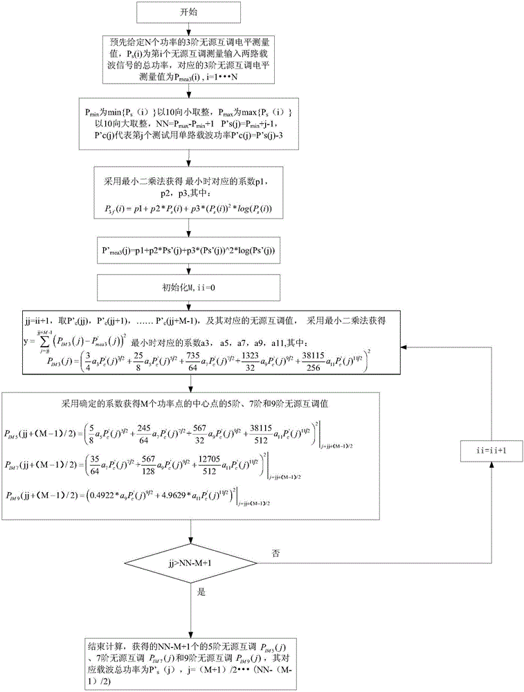
[0066] (1), N=47; given the passive intermodulation measurement value of the third order, the first column is P s (i), the second column is the corresponding third-order passive intermodulation measurement level P mea3 (i), i=1...N.

[0067]

[0068]

[0069] (2), the total number of passive intermodulation power points in the set power variation range NN=31, P min =20,P max =50, P's(j)=j+19, P'c(j)=j+16, j=1...NN.

[0070] (3), using the least squares method to obtain The corresponding coefficients p1, p2, p3 at the minimum, where: P 3f The expression of (i) is as follows:

[0071] P 3f (i)=p1+p2*P s (i)+p3*(P s (i)) 2 *log(P s (i))i=1...N;

[0072] get:

[0073] p1=-186.097323058506;

[0074] p2=3.66221275703211;

[0075] p3=-0.00675616299861527;

[0076] (4), according to the coefficients p1, p2, p3, the measured value P of the third-order passive intermodulation level is obtained by the following formula mea3 Corrected value P' of (i) mea3 (j):

[...


PUM


Abstract

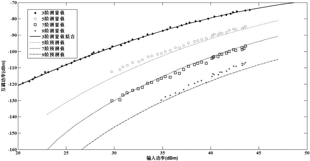
The invention relates to a method for determining high-order passive intermodulation level with a wide power variation range of a microwave component. The method comprises the steps of firstly carrying out polynomial fitting on measured values of three-order passive intermodulation level of the microwave component and the sum of carrier power, carrying out parameter estimation on a power series expansion of a variation relation of the three-order passive intermodulation level along with the power by sequentially adopting an odd number of power and intermodulation level measured values by taking an integer rounded towards the less by a minimum value of the sum of the carrier power as the starting power, taking an integer rounded towards the greater by a maximum value of the sum of the carrier power as the ending power, taking the carrier power of high-order passive intermodulation to be predicted as a center based on a fitted variation curve of the three-order passive intermodulation level along with the sum of the carrier power so as to realize prediction for the high-order passive intermodulation level. The method provided by the invention realizes accurate prediction for the high-order passive intermodulation with a wide power variation range of the microwave component, and an effective means is provided for a follow-up model to carry out evaluation on the high-order passive intermodulation level of the microwave component under the condition that a high-order passive intermodulation testing system is unavailable.

Description

technical field [0001] The invention relates to a method for determining the high-order passive intermodulation level of microwave components in a wide power variation range, and belongs to the field of passive intermodulation of microwave components. Background technique [0002] Passive-Intermodulation (PIM) refers to the combination of carrier frequency due to the mutual modulation of carrier signals caused by the nonlinearity of microwave passive components when two or more carriers are input under high power conditions. The product falls into the receiving passband and causes interference. When the intermodulation level is low, it will increase the noise floor of the received signal, reduce the signal-to-noise ratio of the receiver, and increase the bit error rate; when the intermodulation level is further When it is increased, it will affect the normal operation of the entire communication system, and it is forced to reduce power usage or use it in separate channels; i...

Claims


Application Information

Patent Timeline
IPC IPC(8): G01R31/00
CPCG01R31/001
Inventor 王新波魏焕崔万照李韵陈翔李军李永东
Owner XIAN INSTITUE OF SPACE RADIO TECH
Learn More