A high-precision objective lens parfocal detection device and detection method
A kind of testing equipment and high-precision technology, which is used in the testing of machine/structural components, measuring devices, optical instrument testing, etc. Effects of multi-function operation
- Summary
- Abstract
- Description
- Claims
- Application Information
AI Technical Summary
Problems solved by technology
Method used
Image
Examples
Embodiment 1
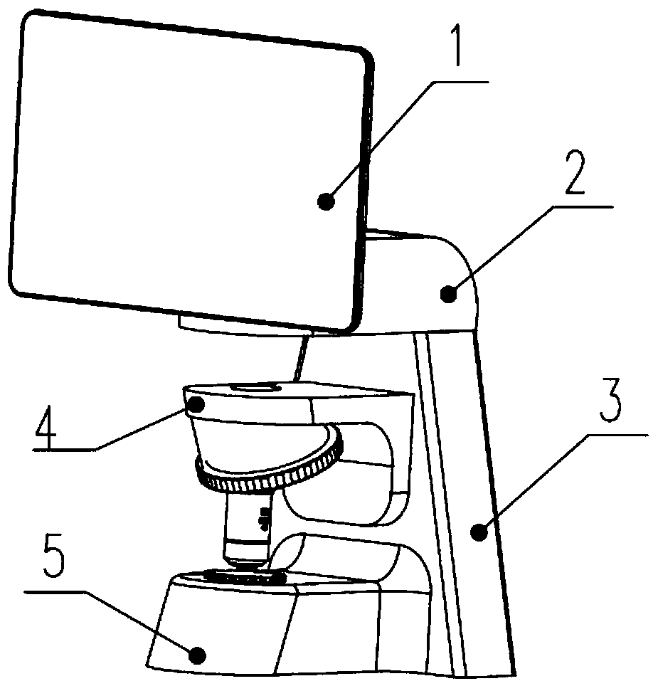
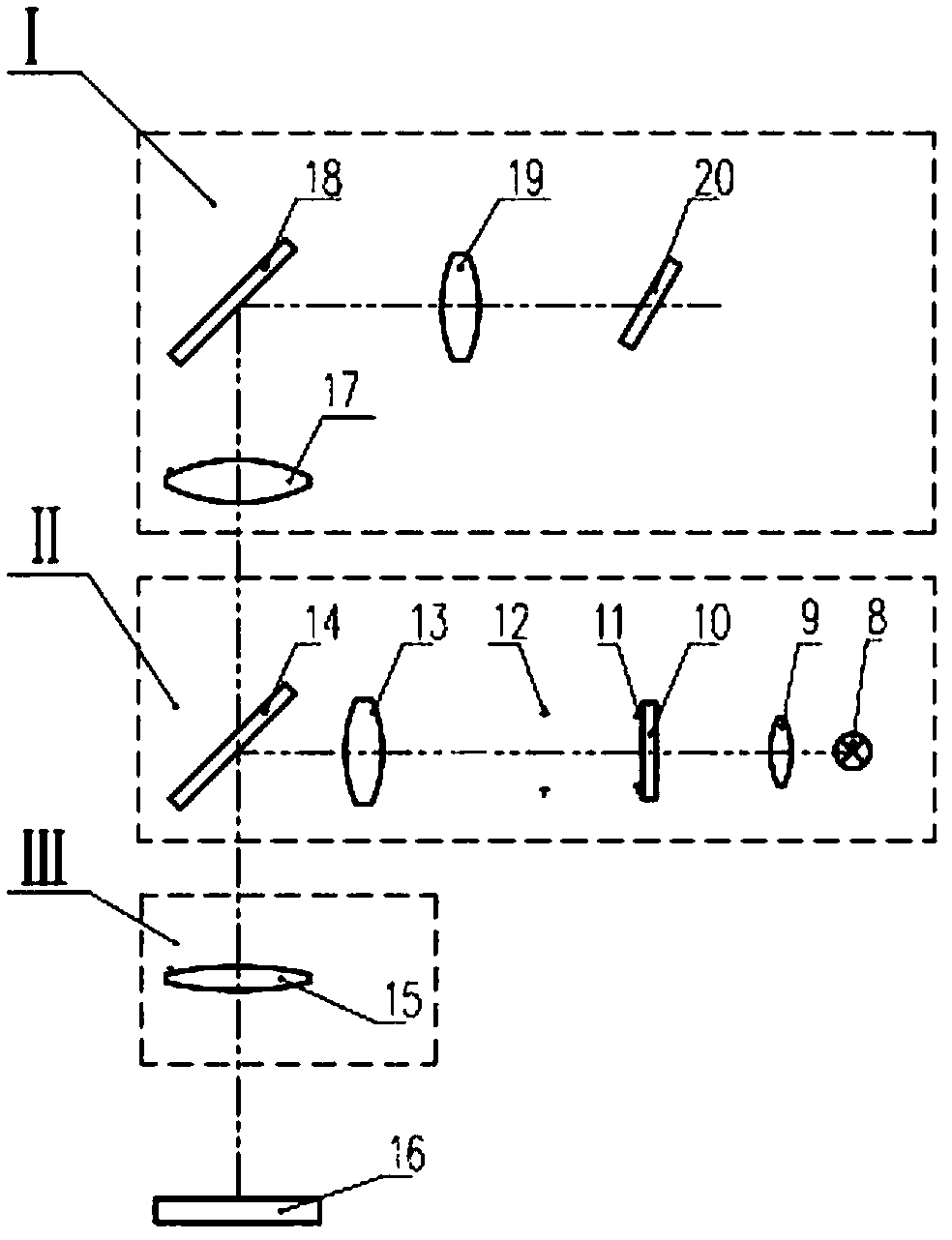
[0061] figure 1 It is the general assembly drawing of the upright digital observation device of this device. As shown in the figure, the detection intermediate 2 includes an epi-bright field coaxial projection system and an oblique imaging system. The standard reticle of the coaxial projection system is placed perpendicular to the optical axis, and the image sensor of the oblique imaging system is placed oblique to the optical axis. Through the algorithm of the image sensor itself, the value can be directly read on the display screen 1, thereby realizing the detection of the parfocal distance. The bracket 4 can be positioned at different parfocal distances, and has a porous objective lens converter, which facilitates the detection of multiple objective lenses. The electrical control group is fixed inside the frame 3 in a built-in manner, which greatly simplifies the wiring of external electric wires inside the frame to achieve the purpose of safety and beauty. The standard re...
Embodiment 2
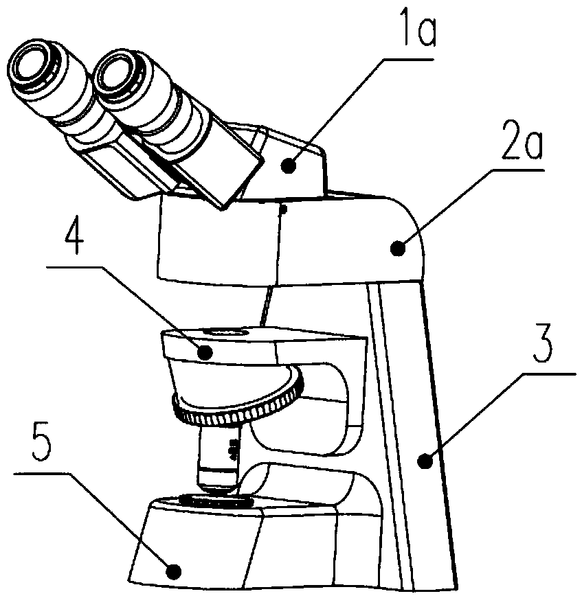
[0079] image 3 It is the general assembly drawing of this device for vertical visual observation. As shown in the figure, the detection intermediate 2a contains an epi-bright field coaxial projection system and an oblique imaging system. The standard reticle of the field coaxial projection system is placed obliquely on the optical axis, and the image sensor of the imaging system is placed vertically on the optical axis. The value can be directly interpreted through the visual head 1a, or it can be connected to a computer to directly read the value on the display screen. The observation mode is selected according to user needs. Bracket 4 can be positioned at different parfocal distances, and has a multi-hole converter to facilitate the detection of multiple objective lenses. The electrical control group is fixed inside the frame 3 in a built-in manner, which greatly simplifies the wiring of external electric wires inside the frame to achieve the purpose of safety and beauty. ...
Embodiment 3
[0090] Figure 5 It is the general assembly drawing of the inverted digital observation device, as shown in the figure, the objective lens is installed on the base 5a porous nosepiece, the bracket 4b is connected to the standard reflector, and can be positioned at different parfocal distances, convenient for various types Inspection of the objective lens. The detection intermediate adopts a built-in design, which is built into the base 5a, and contains an epi-brightfield coaxial projection system and an imaging system. The standard reticle of the coaxial projection system is placed vertically to the optical axis, and the image sensor of the imaging system is inclined to light. Axis placement, through the algorithm of the image sensor itself, the value can be read directly on the display screen 1b, so as to realize the detection of the parfocal distance. The electrical control group is fixed inside the frame 3a in a built-in manner.
[0091] Next, the specific implementation ...
PUM
 Abstract
Description
Claims
Application Information
 - R&D Engineer
- R&D Manager
- IP Professional
- Industry Leading Data Capabilities
- Powerful AI technology
- Patent DNA Extraction
Browse by: Latest US Patents, China's latest patents, Technical Efficacy Thesaurus, Application Domain, Technology Topic, Popular Technical Reports.
© 2024 PatSnap. All rights reserved.Legal|Privacy policy|Modern Slavery Act Transparency Statement|Sitemap|About US| Contact US: help@patsnap.com


