
A double-row multi-axle pile machine

A pile driver and frame technology, which is applied in the field of double-row multi-axis pile drivers, can solve problems such as unreported, and achieve the effects of good stability, convenient operation, and reduced structural strength requirements.

Inactive Publication Date: 2018-01-23
陈腊根
View PDF7 Cites 0 Cited by
  • Summary
  • Abstract
  • Description
  • Claims
  • Application Information

AI Technical Summary

Problems solved by technology

A pile driver that can have a maximum of six shafts in double rows, which has not been reported in existing patents or published documents

Method used


Image

  • A double-row multi-axle pile machine
  • A double-row multi-axle pile machine
  • A double-row multi-axle pile machine

Examples


Embodiment 1

[0038] Example 1: Horizontal arrangement of I-shaped tower

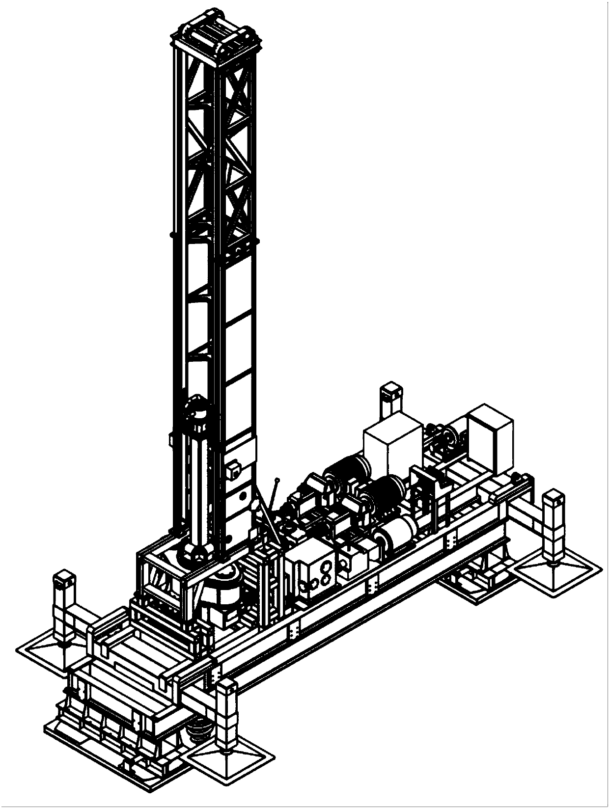
[0039] When the I-shaped tower of the double-row multi-axis pile driver of the present invention is arranged horizontally, the pile type can be processed such as Figure 5 Shown, including: "first three after three", "first three after two", "first two after three", "first two after two", "first one after two", "first two after one" or "first one" The double-row pile type with any combination of "the latter" and other types has the beneficial effect of increasing the pile-forming operation and adapting to the maximum possible size requirements of the actual pile spacing array.

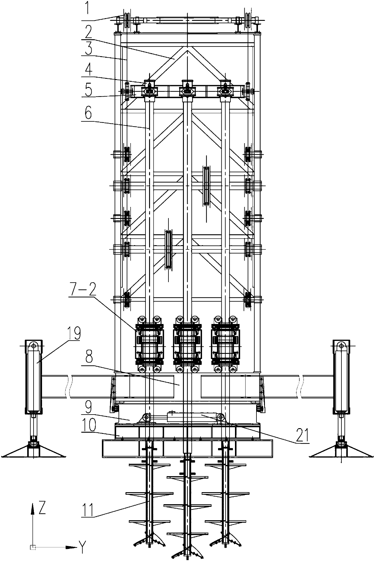
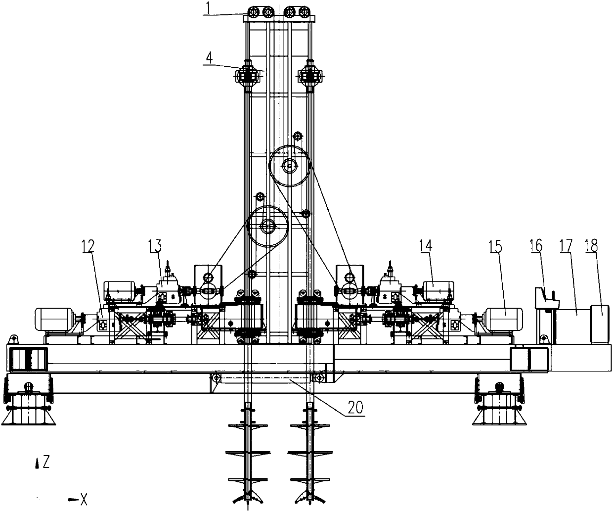
[0040] See attached Figure 2~4 , A double-row multi-axis pile machine, including: sprocket 1, I-shaped tower 2, two sets of lifting chains 3, six rotating heads 4, rotating head frame one 5 and rotating head frame two, six hollow drill rods 6. Six sets of bottom-mounted square turntables, the bottom-mounted square turntables are straight square t...

Embodiment 2

[0054] Example 2: Longitudinal arrangement of I-shaped tower

[0055] See attached Figure 6-8 , When the I-shaped tower 2 is arranged longitudinally, the pile types that can be processed include: "front two back two", "front one back two", "front two back one" or "front one back one" and other arbitrary combinations Double-row pile type.

[0056] The arrangement of the upper frame 8, the lower frame 9, the ram 10, the longitudinal movement cylinder 20, the lateral movement cylinder 21, four supporting legs 19, a set of hydraulic and electric operation table 16, the hydraulic oil tank 17 and the electric control cabinet 18 The first embodiment is the same.

[0057] Setting: The horizontal direction of the double-row multi-axis pile driver is the Y-axis direction, the longitudinal direction is the X-axis direction, and the height is the Z-axis direction; Figure 8 In the illustrated I-shaped tower 2, the neutral plane is parallel to the X axis.

[0058] See attached Figure 6-8 , Wh...


PUM


Abstract

The invention discloses a double-row multi-shaft pile machine which is an important improvement on the basis of the disclosed patent multifunctional ultra-large-diameter stirring pile machine provided with torsion compensation device (ZL201520547506.4). The double-row multi-shaft pile machine can punch six pile holes in two rows at most each time, and the machined pile holes can be distributed transversely or longitudinally. A tower of the pile machine is I-shaped and erected on an upper underframe platform transversely or longitudinally, a row of underneath type square rotary tables are arranged at the lower part of each of two sides of the tower, the number of the square rotary tables in each row is 1-3, one power system drives one or two square rotary tables, the square rotary tables are used for driving hollow drill pipes to rotate forwards or reversely, and every three or two hollow drill pipes share one pressurization system. The pressurization systems are used for driving drill bits to perform pressurization downwards when the hollow drill pipes rotate clockwise to drill downwards or perform pressurization upwards when the hollow drill pipes rotate anticlockwise and the drill bits are lifted. The pile machine is good in stability, high in adaptability, high in operation efficiency, capable of meeting requirements of different pile models and high in cost performance, and the quality of formed piles is high.

Description

Technical field [0001] The invention relates to a double-row multi-axle pile machine, in particular to a double-row multi-axle pile machine capable of simultaneously driving double-row multi-axle piles. It belongs to the technical field of piling machinery and equipment in the construction machinery industry. Background technique [0002] Among the commonly used foundation treatment methods in existing buildings, the pile-handling methods for bearing piles include: cement-soil mixing piles and perforated cast-in-place piles. The cement-soil mixing piles use cement as a curing agent and are used in the deep part of the foundation through a deep mixer. The soft soil and solidifying agent (slurry or powder) are forced to stir and mix, and a series of physical and chemical reactions occur between the solidifying agent and the soft soil to condense into cement with integrity, good water stability and higher strength. , Forming a composite foundation with the natural foundation, or as...

Claims


Application Information

Patent Timeline
Patent Type & Authority Patents(China)
IPC IPC(8): E02D5/46E21B3/02E21B15/00E21B19/00
CPCE02D5/46E21B3/02E21B15/00E21B19/00
Inventor 陈腊根
Owner 陈腊根
Learn More