
A circular hoisting tool

A hoisting tool and hoisting part technology, used in cranes and other directions, can solve the problems of large base occupied space, single use range, long power failure cycle, etc., to achieve the effect of improving work efficiency, reducing power failure range and reducing power failure cycle.

Inactive Publication Date: 2017-12-01
STATE GRID SHANDONG ELECTRIC POWER CO LAIZHOU POWER SUPPLY CO
View PDF1 Cites 0 Cited by
  • Summary
  • Abstract
  • Description
  • Claims
  • Application Information

AI Technical Summary

Problems solved by technology

[0005] The purpose of the present invention is to provide a circular hoisting tool for the deficiencies of the prior art, which solves the problems of single use range, large base occupation space, large operating radius, wide power failure range, low work efficiency and long power failure period in the prior art. question

Method used


Image

  • A circular hoisting tool
  • A circular hoisting tool
  • A circular hoisting tool

Examples


Embodiment 1

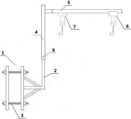
[0024] Example one: figure 1 , image 3 As shown, a schematic structural diagram of a circulating hoisting tool of the present invention includes a supporting part and a hoisting part. The supporting part includes a base 1 and a first main rod 2 fixed on the base 1. The base 1 is provided with an adjustable The bolt 3 is composed of two steel plates. The hoisting part includes a second main rod 4 and a cantilever 5. The second main rod 4 and the first main rod 2 are sleeved together to connect the two parts, and the cantilever 5 is fixedly connected to The upper end of the second main rod 4 and the second main rod 5 are at an angle of 90°. The cantilever 5 has an annular shape and is provided with a guide rail. The guide rail is provided with a first electric hoist 6 and a second The electric hoist 7 can slide on the cantilever 5, and a steel ball 8 is installed in the gap between the first electric hoist 6 and the second electric hoist 7 on the guide rail.

[0025] Figure 4 As ...

Embodiment 2

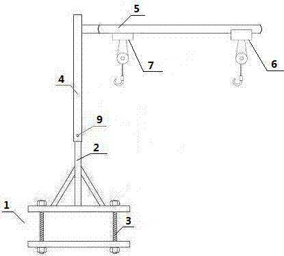
[0035] Embodiment two: figure 2 As shown, a schematic structural diagram of a circulating hoisting tool of the present invention includes a supporting part and a hoisting part. The supporting part includes a base 1 and a first main rod 2 fixed on the base 1. The base 1 is provided with an adjustable The bolt 3 is composed of two steel plates. The hoisting part includes a second main rod 4 and a cantilever 5. The second main rod 4 and the first main rod 2 are sleeved together to connect the two parts, and the cantilever 5 is fixedly connected to The upper end of the second main rod 4 and the second main rod 5 are at an angle of 90°. The cantilever 5 has an annular shape and is provided with a guide rail. The guide rail is provided with a first electric hoist 6 and a second The electric hoist 7 can slide on the cantilever 5, and a steel ball 8 is installed in the gap between the first electric hoist 6 and the second electric hoist 7 on the guide rail.

[0036] Figure 5 As shown, ...


PUM


Abstract

The invention discloses a cyclic hoisting tool and relates to the field of hoisting. The cyclic hoisting tool comprises a supporting part and a hoisting part. The supporting part comprises a base (1) and a first main rod (2) fixed on the base (1), wherein the base (1) consists of two steel plates provided with adjustable bolts (3); the hoisting part comprises a second main rod (4) and a cantilever (5); the second main rod (4) and the first main rod (2) are sleeved for connecting the two parts; the cantilever (5) is circular and is provided with a guide rail; an electric hoist (6) and an electric hoist (7) which are opposite to each other are arranged on the guide rail and can slide on the cantilever (5); steel balls (8) are arranged at a gap between the electric hoist (6) and the electric hoist (7) on the guide rail. The hoisting tool has the advantages that the service range is wide; and the occupied space of the base is small, the operation radius is small, the power outage range is narrowed, and the working efficiency is greatly improved, thereby shortening the power outage cycle.

Description

Technical field [0001] The invention relates to the field of hoisting, in particular to a circulating hoisting tool. Background technique [0002] With the growth of service life, substations often face renovation and renewal, and the renovation project of substations requires the replacement of old outdoor equipment, such as voltage transformers, switchgear, arresters and other outdoor equipment, which are usually installed on the structure However, the outdoor substation equipment is large in size, heavy in weight, and difficult to carry by manpower. It usually needs to be hoisted by a crane. According to the "State Grid Corporation Electric Safety Work Regulations", crane operation requires a certain working radius, and the relative equipment is replaced. All adjacent compartments need to be powered off. This will inevitably expand the scope of power outages, directly affect the normal power supply, and then affect people's normal life. [0003] We analyzed the actual situation...

Claims


Application Information

Patent Timeline
Patent Type & Authority Patents(China)
IPC IPC(8): B66C23/16B66C23/78
CPCB66C23/163B66C23/78
Inventor 聂培生蔡登科杨锡宝高维强孙志芳林鹏飞程永香邓利民杨文祥王鑫翟大力邱世林孙军红周绍芬杜卫国朱良刘志杰周广波
Owner STATE GRID SHANDONG ELECTRIC POWER CO LAIZHOU POWER SUPPLY CO
Learn More