Cyclic hoisting tool
A hoisting tool and hoisting part technology, which is applied to cranes and other directions, can solve the problems of large space occupied by the base, single use range, and large operating radius, and achieve the effects of improving work efficiency, reducing the scope of power outages, and reducing the operating radius
- Summary
- Abstract
- Description
- Claims
- Application Information
AI Technical Summary
Problems solved by technology
Method used
Image
Examples
Embodiment 1
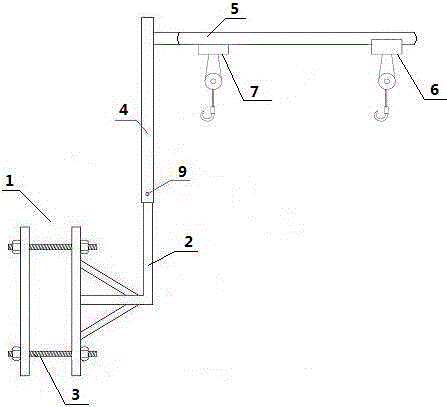
[0024] Example 1: figure 1 , image 3 As shown, a schematic structural diagram of a circulating hoisting tool of the present invention includes a support part and a hoisting part, the support part includes a base 1 and a first main rod 2 fixed on the base 1, and the base 1 is provided with an adjustable The bolt 3 is composed of two steel plates, the hoisting part includes a second main rod 4 and a cantilever 5, the second main rod 4 is assembled with the first main rod 2 to connect the two parts, and the cantilever 5 is fixedly connected to the The upper end of the second main rod 4 is at an angle of 90° with the second main rod 5 , the cantilever 5 is in a ring shape, and is provided with a guide rail. Sliding on the cantilever 5, steel balls 8 are installed in the gap between the electric hoist 6 and the electric hoist 7 on the guide rail.
[0025] Figure 4 As shown, a schematic structural diagram of the support part of a circulating lifting tool of the present inventio...
Embodiment 2
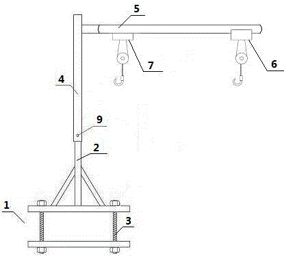
[0035] Embodiment 2: figure 2 As shown, a schematic structural diagram of a circulating hoisting tool of the present invention includes a support part and a hoisting part, the support part includes a base 1 and a first main rod 2 fixed on the base 1, and the base 1 is provided with an adjustable The bolt 3 is composed of two steel plates, the hoisting part includes a second main rod 4 and a cantilever 5, the second main rod 4 is assembled with the first main rod 2 to connect the two parts, and the cantilever 5 is fixedly connected to the The upper end of the second main rod 4 is at an angle of 90° with the second main rod 5 , the cantilever 5 is in a ring shape, and is provided with a guide rail. Sliding on the cantilever 5, steel balls 8 are installed in the gap between the electric hoist 6 and the electric hoist 7 on the guide rail.
[0036] Figure 5 As shown, a schematic structural diagram of the support part of a circulating lifting tool of the present invention, the s...
PUM
 Abstract
Description
Claims
Application Information
 - R&D
- Intellectual Property
- Life Sciences
- Materials
- Tech Scout
- Unparalleled Data Quality
- Higher Quality Content
- 60% Fewer Hallucinations
Browse by: Latest US Patents, China's latest patents, Technical Efficacy Thesaurus, Application Domain, Technology Topic, Popular Technical Reports.
© 2025 PatSnap. All rights reserved.Legal|Privacy policy|Modern Slavery Act Transparency Statement|Sitemap|About US| Contact US: help@patsnap.com


