Pre-tensioned prefabricated track board synchronous extension device and implementing method thereof

A track plate and pre-tensioning technology, applied in the direction of manufacturing tools, ceramic molding machines, etc., can solve the problems of inability to disassemble the device, transfer and reinstall, inability to achieve vertical and horizontal simultaneous tensioning, and uneven distribution of prestress, so as to shorten the production cycle , improve the efficiency of release, and achieve the effect of repeated use

Active Publication Date: 2016-11-09
RAILWAY ENG RES INST CHINA ACADEMY OF RAILWAY SCI +3
View PDF7 Cites 10 Cited by
  • Summary
  • Abstract
  • Description
  • Claims
  • Application Information

AI Technical Summary

Problems solved by technology

[0004] When over-tensioned, the prestressed steel bars and the solidified concrete will cause damage, and the production efficiency is low, the floor area is large, and the vertical and horizontal simultaneous tensioning cannot be achieved, the prestress distribution is uneven, and the product deformation is large; at the same time , the tensioning and releasing devices of the traditional "platform method" all need to build a concrete load-bearing foundation pit, which cannot realize the disassembly, transfer and reinstallation of the device

Method used


Image

  • Pre-tensioned prefabricated track board synchronous extension device and implementing method thereof
  • Pre-tensioned prefabricated track board synchronous extension device and implementing method thereof
  • Pre-tensioned prefabricated track board synchronous extension device and implementing method thereof

Examples


Embodiment Construction

[0086] In order to better explain the present invention and facilitate understanding, the present invention will be described in detail below through specific embodiments in conjunction with the accompanying drawings.

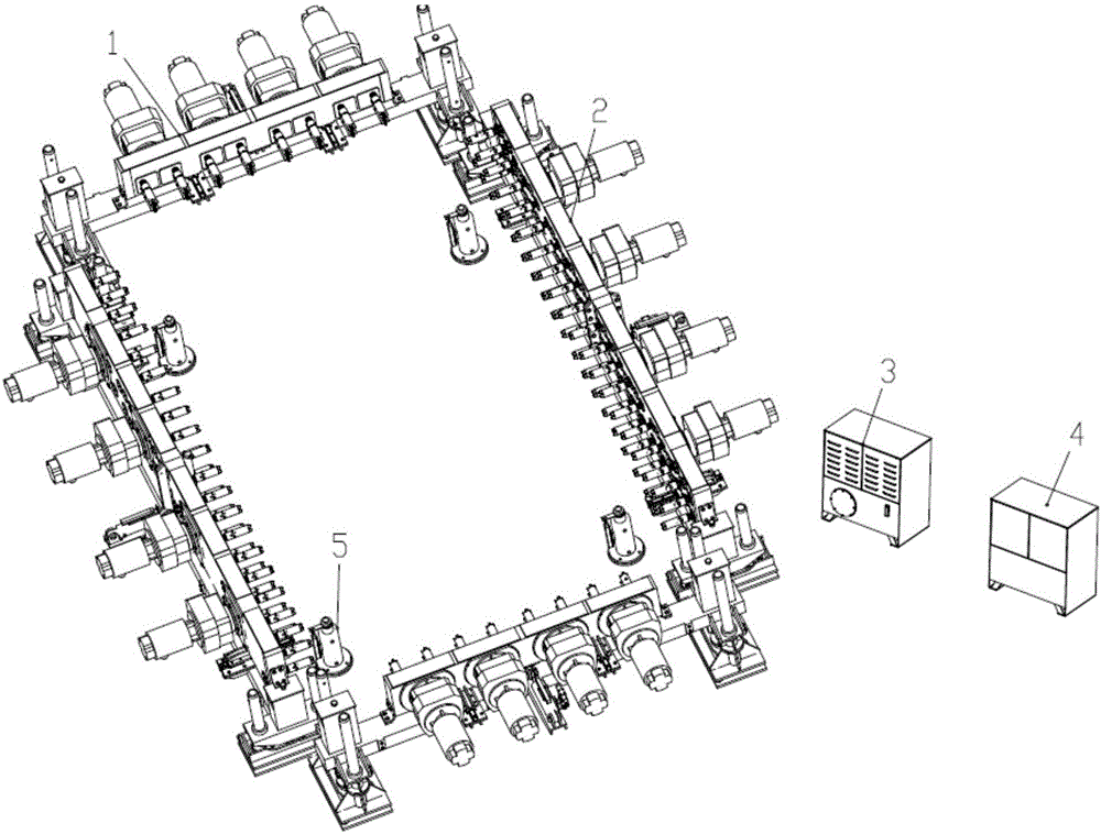
[0087] The present invention mainly realizes synchronous vertical and horizontal stretching by arranging a stretching mechanism on the end face and side of the track plate, and cooperating with the mold positioning device.

[0088] Specifically, the present invention provides a synchronous stretching device for pre-tensioned prefabricated track slabs, which includes:

[0089] The end stretching mechanism is installed on the working surface along the first installation direction, and has an end power unit for stretching. The end stretching mechanism has a first stretching direction for the end power unit to stretch, and is for adjustment The first adjustment direction for the end power unit;

[0090] The side stretching mechanism, which is installed on the work...


PUM


Abstract

The invention relates to a pre-tensioned prefabricated track board synchronous extension device and an implementing method thereof. The device comprises an end extension mechanism, a side extension mechanism, a pump station, an electric control cabinet and a die positioning device. The method includes the steps of a, leveling and correcting the synchronous extension device and precisely installing the synchronous extension device on an extension station; b, making a die enter the right position, and leveling the die to be in place through the die positioning device; c, adjusting the end extension mechanism and the side extension mechanism to be aligned with tension connection rods of the two sides and the two ends of the die; d, starting an extension power mechanism to rotate reversely, making an extension sleeve meshed with the tension connection rods by horizontally aligning oil cylinders through the end extension mechanism and the side extension mechanism; e, making the oil cylinders in place to drive an end box body and a side box body to move along an end slide rail and a side slide rail to the extension station, and stopping the operation after the end extension mechanism and the side extension mechanism are meshed in place; f, controlling the extension power mechanism to rotate forwards, and achieving synchronous extension; g, after completing extension, resetting the end extension mechanism and the side extension mechanism; h, resetting the die. By means of the device, longitudinal-transverse synchronous uniform stable extension of a plurality of reinforcing steel bars with tension stress can be achieved.

Description

technical field [0001] The invention belongs to the technical field of rail transit infrastructure construction, and in particular relates to a device and a method for realizing synchronous tensioning of prestressed steel bars of pre-tensioned prefabricated track slabs after tensioning. Background technique [0002] "Stand method" is a traditional technique of pretensioning prestressed concrete structure construction, in which it is necessary to use a tensioning device for prestressed steel bars, use a tensioning jack to over-stretch the prestressed steel bars, and then loosen the nuts of the connecting rods of the stressed steel bars. [0003] Above-mentioned technology still has following deficiency: [0004] When over-tensioning, the prestressed steel bars and the solidified concrete will cause damage, and the production efficiency is low, the floor area is large, and the vertical and horizontal simultaneous tensioning cannot be realized, the prestress distribution is une...

Claims


Application Information

Patent Timeline
IPC IPC(8): B28B23/04
CPCB28B23/04
Inventor 王继军张松琦吴元文钱振地张长春王梦王舒毅税卓平崔进福张远庆赵勇施成陈冰燕
Owner RAILWAY ENG RES INST CHINA ACADEMY OF RAILWAY SCI
Why Eureka
Try Eureka