
a salt therapy device

A salt therapy device and salt therapy technology, applied in the field of salt therapy devices

Active Publication Date: 2019-10-22
江苏春帆生物科技有限公司
View PDF10 Cites 0 Cited by
  • Summary
  • Abstract
  • Description
  • Claims
  • Application Information

AI Technical Summary

Problems solved by technology

[0004] The object of the present invention is to aim at the above-mentioned defect of prior art, propose a kind of halotherapy device, increase negative oxygen ion generating device on the basis of halotherapy device, combine salt therapy and negative oxygen ion organically, change halotherapy device single-function defect

Method used


Image

  • a salt therapy device
  • a salt therapy device

Examples


Embodiment Construction

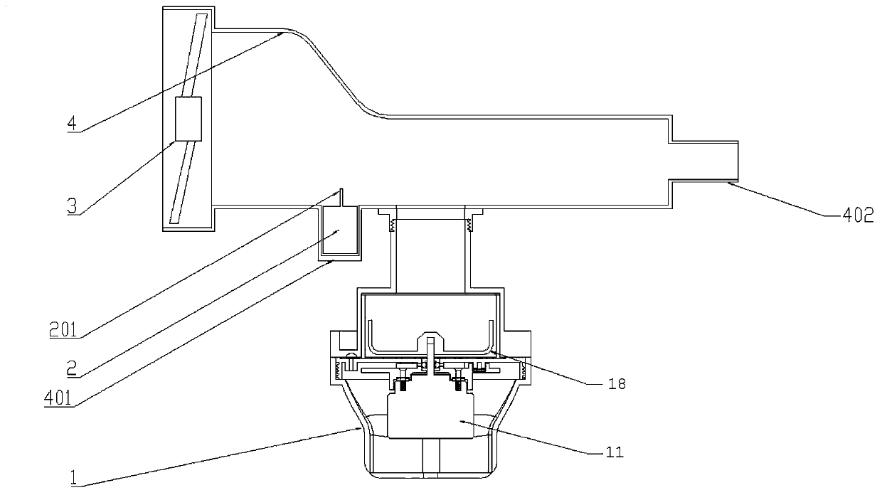
[0020] Such as figure 1 As shown, the salt therapy device according to the present invention includes: a grinding system, a fan 3 and an air duct 4 . In addition, a negative oxygen ion generating device 2 is also included.

[0021] Wherein, the fan 3 is placed on the left side of the air duct 4 to blow air into the air duct 4 .

[0022] Such as figure 1 As shown, the grinding system includes a cutter 18 and a motor 11. The grinding system is connected with the air duct 4, and the micron-sized aerosol that is ground out is discharged to the right outlet 402 through the air duct 4 and enters the salt therapy environment.

[0023] Inside the air duct 4, a tank box 401 is provided between the grinding system and the fan 3, but not limited to the middle part. The negative oxygen ion generator 2 is placed inside the tank box 401. The negative ions ionized by the oxygen ion generating device 2 enter the salt therapy environment together with the oxygen in the air and the aerosol....


PUM


Abstract

The invention provides a novel salt therapy apparatus, comprising a grinding system, a fan, an air pipe and an anion generator, wherein the grinding system is of top-set structure or bottom-set structure. The novel salt therapy apparatus according to the invention is added with the anion generator based on a salt therapy apparatus to organically combine salt therapy with anions; the structure of the grinding system is also improved, tools are easier to clean, and work efficiency is improved.

Description

technical field [0001] The invention relates to a salt therapy device, which belongs to the field of medical equipment. Background technique [0002] At present, the method of treating respiratory diseases through the salt mist aerosol generated by the halotherapy device has been widely used in the medical field, but at this stage, the halotherapy equipment can only generate aerosol and release it into the halotherapy environment, and the salt treatment Effect, no other physiotherapy effect, single function. [0003] In addition, the medical salt spray equipment in the salt therapy room uses a salt mill to grind the salt into powder and spray it after atomization. However, the existing grinding system mostly adopts the hanging structure, which is not conducive to the disassembly of the user, and the motor , blades, and grinding bins are integrated into one component, which is placed at the lower part of the air duct of the salt therapy device, making it cumbersome to clean ...

Claims


Application Information

Patent Timeline
Patent Type & Authority Patents(China)
IPC IPC(8): A61M15/02A61M15/00A61N1/44
Inventor 李天宇
Owner 江苏春帆生物科技有限公司
Learn More