Acquisition control for mixed mode ultrasound imaging

A mixed mode, ultrasonic imaging technology, applied in the direction of ultrasonic/sonic/infrasonic equipment control, structure of ultrasonic/sonic/infrasonic diagnostic equipment, ultrasonic/sonic/infrasonic diagnosis, etc., can solve the problem of increasing the examination duration

Inactive Publication Date: 2016-11-09
SIEMENS MEDICAL SOLUTIONS USA INC
View PDF11 Cites 11 Cited by
  • Summary
  • Abstract
  • Description
  • Claims
  • Application Information

AI Technical Summary

Problems solved by technology

This type of workflow greatl...

Method used


Image

  • Acquisition control for mixed mode ultrasound imaging
  • Acquisition control for mixed mode ultrasound imaging
  • Acquisition control for mixed mode ultrasound imaging

Examples


Embodiment Construction

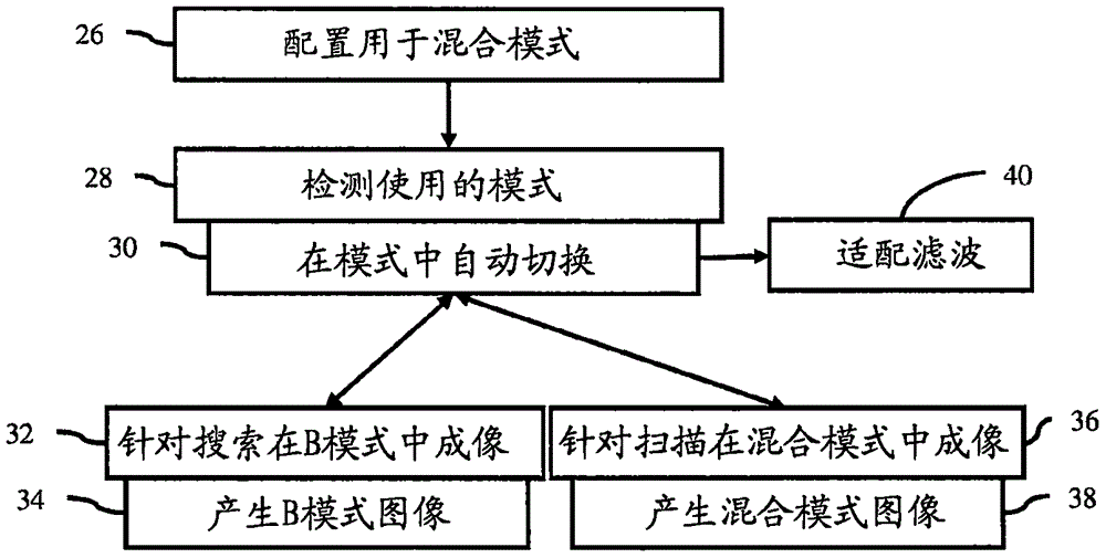
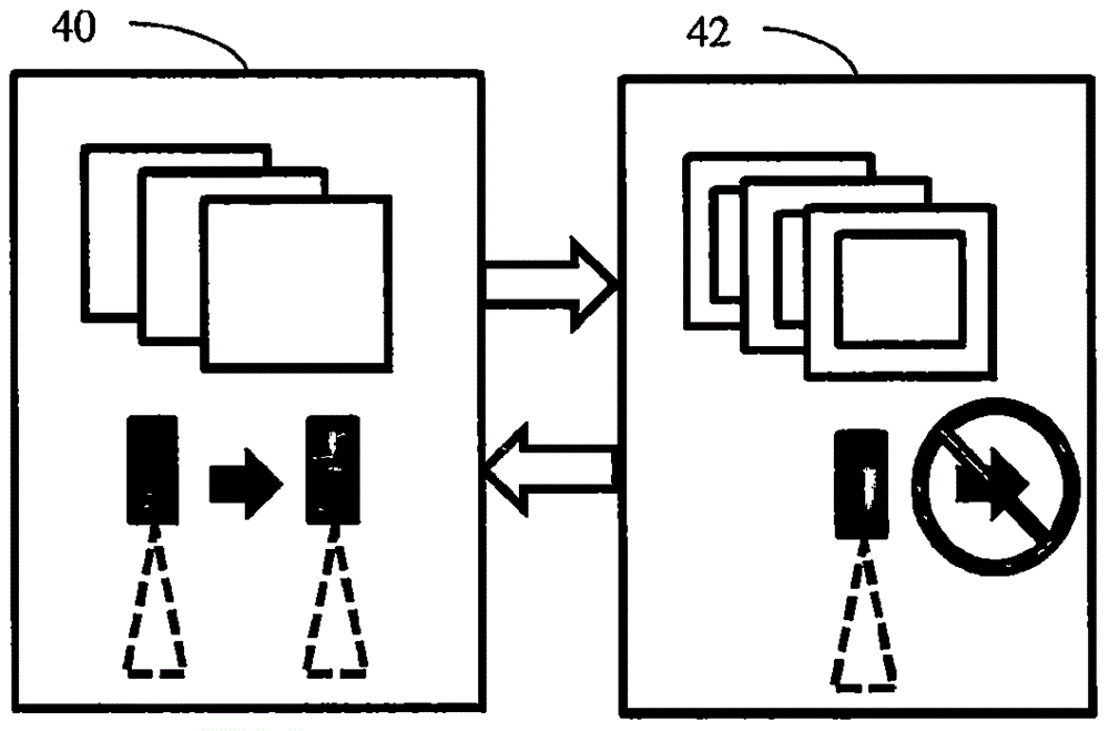
[0011] Improved workflow in mixed-mode medical ultrasound imaging. During the "search" or "find" mode, the sonographer tries to find the best angle or transducer window for the region of interest. In this search mode but also in a mixed mode configuration, although configured for mixed mode imaging, the mixed mode is temporarily disabled. Provides excellent B-mode image quality to find the best scan position with higher frame rates. During Flow or Sweep mode, blend mode is enabled. This eliminates the need for the operator to switch to B-mode or vice versa before returning to hybrid mode.

[0012] In one embodiment, automatic switching between B-mode and color flow mode turns color flow mode on and off based on whether the user is in search mode or scan mode. Search patterns can be detected by, but not limited to, frame correlation, tissue contact, and / or brightness of the image. Restores B-mode quality and / or frame rate during seek mode to increase user responsiveness. A...


PUM


Abstract

The invention relates to acquisition control for m mixed mode ultrasound imaging. For mixed mode imaging (36), an ultrasound scanner distinguishes (28) between times when different modes of imaging (32, 36) are appropriate based on motion or transducer usage. Any switching (30) between modes, such as between B-mode and mixed mode imaging (32, 36), occurs automatically based on the detection by the ultrasound scanner of motion, alleviating the need for sonographer manual selection.

Description

Background technique [0001] This embodiment relates to mixed-mode ultrasound imaging. During a typical ultrasound scanning session, the sonograph frequently switches between B-mode and mixed-mode imaging. Hybrid modes may include B-mode (ie, Doppler mode) combined with color flow. One reason for switching modes frequently, especially for low-end systems, is that B-mode image quality and / or frame rate is reduced when in hybrid mode due to hardware and / or software limitations. To find an area for mixed-mode imaging, the user selects B-mode imaging with a correspondingly better frame rate and / or image quality. Once found, the user selects a hybrid mode with poorer B-mode image quality but with additional imaging modes. This process can be repeated during imaging sessions. This type of workflow greatly increases the inspection duration. Contents of the invention [0002] By way of introduction, the preferred embodiments described below include methods, instructions, and sys...

Claims


Application Information

Patent Timeline
IPC IPC(8): A61B8/00
CPCA61B8/44A61B8/5261A61B8/54A61B8/4416A61B8/5246A61B8/488A61B8/486A61B8/14
Inventor S·多德C·H·徐王景源
Owner SIEMENS MEDICAL SOLUTIONS USA INC
Why Eureka
Try Eureka