Agricultural Harvester Auger Assembly

A screw conveyor, harvester technology, applied in the direction of harvesters, agricultural machinery and implements, agriculture, etc., can solve problems such as reducing the capacity of combine harvesters, and achieve the effect of reducing volume and weight requirements and enhancing filling efficiency.

Active Publication Date: 2016-11-09
CNH IND MASCH (HARBIN) CO LTD
View PDF6 Cites 0 Cited by
  • Summary
  • Abstract
  • Description
  • Claims
  • Application Information

AI Technical Summary

Problems solved by technology

Therefore, placing the open groove auger close to the cleaning fan outlet reduces the capacity of the combine harvester

Method used


Image

  • Agricultural Harvester Auger Assembly
  • Agricultural Harvester Auger Assembly
  • Agricultural Harvester Auger Assembly

Examples


Embodiment Construction

[0020] The terms "grain", "straw" and "tails" are used throughout the specification primarily for convenience, it being understood that these terms are not limiting. Thus, "grain" refers to the portion of crop material that is threshed and separated from the discardable crop material fraction, known as non-cereal crop material, MOG or straw. Incompletely threshed crop material is known as "tailings". Additionally, the terms "front", "rear", "left" and "right" when used in connection with an agricultural harvester and / or components thereof, are generally defined with respect to the forward operating direction of travel of the harvester, but this is not Should be restrictive. The terms "longitudinal" and "transverse" are determined with respect to the fore-aft direction of the agricultural harvester, and likewise should not be limiting.

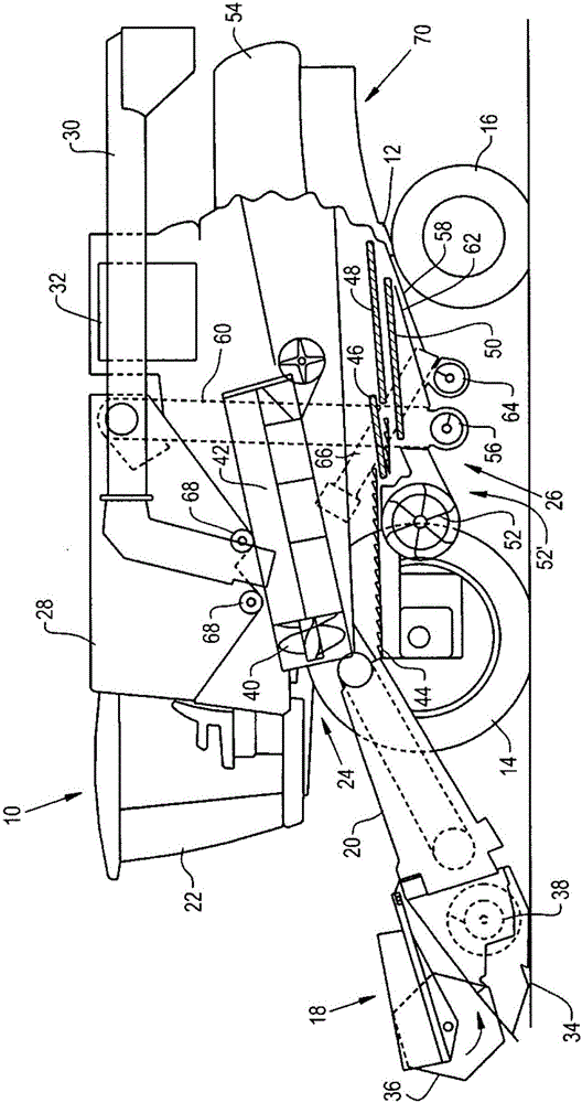
[0021] Referring now to the accompanying drawings, and more specifically to figure 1 , which shows an agricultural harvesting machine in th...


PUM


Abstract

An agricultural harvester includes an auger assembly including an auger having an auger shaft defining an axis of rotation and a flighting carried by the auger shaft, the auger being configured to rotate the flighting in a sweeping path about the axis of rotation; and an auger trough placed adjacent to the auger to hold crop material in the sweeping path and having a bottom below the sweeping path. The auger trough has a first portion on a first side of the bottom and a second portion on a second side opposite the first side of the bottom, with the second portion of the auger trough having an end directed toward the first portion in a direction of the sweeping path.

Description

technical field [0001] The present invention relates to agricultural harvesters, and more particularly, the present invention relates to grooves for augers of agricultural harvesters. Background technique [0002] Combine harvesters are used to harvest agricultural crops such as corn, soybeans, wheat and other cereal crops. As the combine harvester is driven through a field of crops, the combine cuts the crop, separates the desired crop from undesired waste, stores the crop, and discards the waste. [0003] In a typical combine harvester, a header is mounted to the front of the combine to gather the crop together and feed the crop into the combine for processing. As the combine is driven through the field, crop material is collected by the header and deposited into the feeder housing. The crop material is then transported up into the combine by the feed elevator located within the feeder housing. The crop material then passes through the threshing and separating mechanism...

Claims


Application Information

Patent Timeline
Patent Type & Authority Applications(China)
IPC IPC(8): A01D57/00
CPCA01F12/46A01F12/444A01D57/00
Inventor P·王德威尔德D·T·特纳K·R·林德E·E·维科尔
Owner CNH IND MASCH (HARBIN) CO LTD
Why Eureka
Try Eureka