Regenerator for a thermal cycle engine

A technology for regenerators and engines, which is applied in the direction of regenerators, hot gas variable displacement engine devices, engine components, etc., and can solve problems such as the absence of high-efficiency regenerators

Inactive Publication Date: 2016-11-02
NV BEKAERT SA
View PDF10 Cites 0 Cited by
  • Summary
  • Abstract
  • Description
  • Claims
  • Application Information

AI Technical Summary

Problems solved by technology

[0009] The problem with the prior art is that there are no high efficiency regenerators that have varying characteristics in the direction of fluid flow and can be manufactured in a cost-effective manner

Method used


Image

  • Regenerator for a thermal cycle engine
  • Regenerator for a thermal cycle engine
  • Regenerator for a thermal cycle engine

Examples


Embodiment Construction

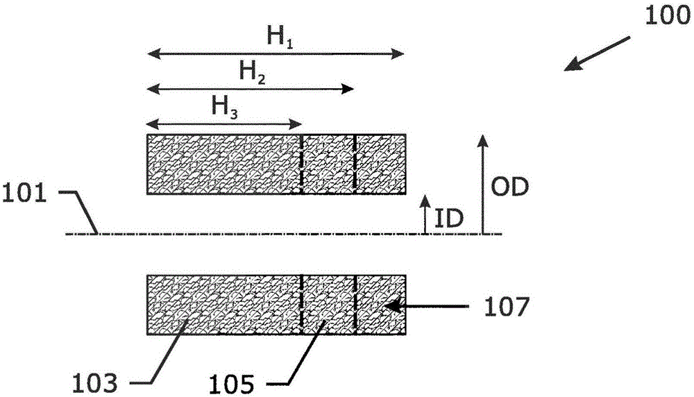
[0048] figure 1 An example 100 of a regenerator ring according to the invention is shown. The regenerator has a central axis 101 of symmetry. The regenerator is at its axial length H 1 have a constant cross-sectional shape and size. The regenerator ring has an axial length H 1 , such as 72mm. The inner diameter is ID, eg 143mm, and the outer diameter is OD, eg 221mm. The regenerator ring has three sections with different levels of porosity: a length H of eg 48 mm with a first porosity of eg 90% 3 The first segment 103; has a length H of porosity higher than the first porosity, for example 92.4% 2 -H 3 (e.g., 60mm-48mm=12mm); and a length H with a higher porosity, e.g., 94.6% 1 -H 2 (eg, 72mm-60mm=12mm) third section 107 .

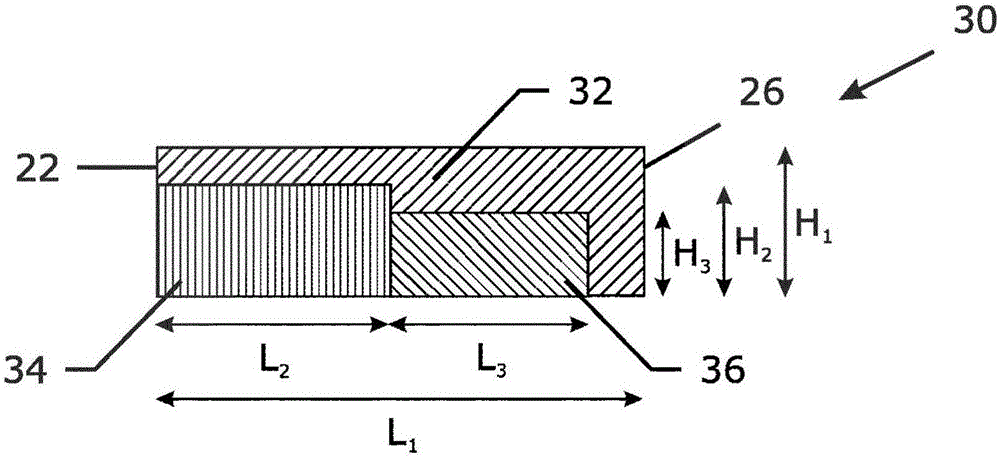
[0049] figure 2 Another example 200 of a regenerator ring according to the invention is shown. The regenerator has a central axis 201 of symmetry. The regenerator at its axial length H of eg 72mm 1 available in different cross-sectional shape...


PUM

PropertyMeasurementUnit
lengthaaaaaaaaaa
porosityaaaaaaaaaa
porosityaaaaaaaaaa

Abstract

The regenerator has a central axis. The regenerator comprises a multitude of web layers wound around the central axis. The web layers are formed by two or more metal fiber or metal wire comprising webs wound around the central axis. When observed from the central axis to the outside of the regenerator, at least one web layer of a web of a first width is followed by a web layer of a web of a width larger than the web of a first width.

Description

technical field [0001] The present invention relates to a regenerator for a thermal cycle engine, such as a stirling engine, and a method for manufacturing such a regenerator. Background technique [0002] Regenerators are used in thermal cycle engines to add or remove heat from the working stream during different phases of the thermal cycle. The regenerator is an important component used to define the efficiency of a thermal cycle engine such as a Stirling engine. [0003] The regenerator needs to have very low thermal conductivity in the direction of fluid flow (along the axis of the regenerator), since one end of the regenerator is hot and the other end is cold. The regenerator needs to have very high thermal conductivity in the direction perpendicular to the fluid flow so that the working flow can quickly adjust itself to the local temperature inside the regenerator. The regenerator must have a very large specific surface area to improve the rate of heat transfer of th...

Claims


Application Information

Patent Timeline
Patent Type & Authority Applications(China)
IPC IPC(8): F02G1/057F28D17/02
CPCF02G1/057B23P15/26F02G2257/00F28D17/02Y10T29/49357
Inventor F·弗夏维
Owner NV BEKAERT SA
Why Eureka
Try Eureka