
Control device for vehicle drive device

A driving device and control device technology, which is applied in the direction of transmission control, road vehicle drive control system, and layout of multiple different prime movers of general power plants, can solve problems such as residual pressure and residual, and reduce uncoordinated problems. Effect

Active Publication Date: 2016-10-26
AISIN AW CO LTD
View PDF5 Cites 4 Cited by
  • Summary
  • Abstract
  • Description
  • Claims
  • Application Information

AI Technical Summary

Problems solved by technology

[0004] However, after reducing the engagement pressure of the release-side engagement device, which is the engagement device that releases to switch gears, residual pressure may remain due to a delay in response.
If the torque of the driving force source is reduced in this state, there is a possibility that negative torque will be transmitted to the wheel side via the release-side engagement device with a remaining transmission torque capacity.

Method used


Image

  • Control device for vehicle drive device
  • Control device for vehicle drive device
  • Control device for vehicle drive device

Examples


Embodiment Construction

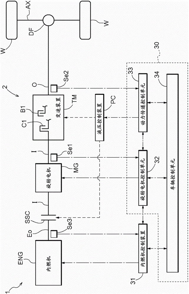
[0046] The control device 30 (hereinafter, simply referred to as "control device 30") of the vehicle drive device 1 according to the embodiment will be described with reference to the drawings. figure 1 It is a schematic diagram showing a schematic configuration of the vehicle drive device 1 and the control device 30 according to the present embodiment. In the figure, a solid line indicates a drive force transmission path, a dotted line indicates a hydraulic oil supply path, and a dotted line indicates a signal transmission path.

[0047] In the vehicle drive device 1 , a transmission device TM is provided on a power transmission path 2 connecting a drive force source and wheels W. As shown in FIG. The transmission device TM includes a plurality of engagement devices C1 , B1 , ··, and selectively forms a plurality of shift speeds with different gear ratios depending on the engaged states of the plurality of engagement devices C1 , B1 , ··.

[0048] In the present embodiment, ...


PUM


Abstract

A control device is provided which performs upshift control in a manner suitable to the torque of the drive power source and so as to suppress reductions in torque transmitted to the wheels via a release-side engagement device even if there is still residual pressure in said release-side engagement device. In inertial phase control, torque reduction control is performed on the torque of the drive power source, and the start time of the torque reduction control relative to the execution time of the torque phase control is changed in accordance with at least the torque of the drive power source before shift start.

Description

technical field [0001] The present invention relates to a control device for controlling a vehicle drive device provided with a transmission device on a power transmission path connecting a driving force source and wheels. The transmission device is provided with a plurality of engagement devices. Selectively form a plurality of gears with different gear ratios according to the engaged state. Background technique [0002] Regarding such a control device as described above, for example, a technology described in Patent Document 1 below is known. In the technology described in Patent Document 1, in the upshift control for switching the gear stage of the transmission device to a gear stage with a relatively small gear ratio, the torque phase control is used to control the engagement pressure of the engagement side engagement device to To increase, while maintaining the increased pressure, the torque of the driving force source is decreased to start a rotational change in which...

Claims


Application Information

Patent Timeline
Patent Type & Authority Applications(China)
IPC IPC(8): B60W10/04B60W10/06B60W10/10B60W10/11B60W20/30F02D29/00F16H59/14F16H61/04F16H63/50
CPCF16H61/061F16H61/686F02D29/02F16H63/502Y10S903/911Y10S903/913Y10S903/914Y10S903/919Y10S903/93B60K6/547B60K2006/4825B60K6/387B60W20/30B60W30/19B60K6/48F16H3/663F16H2200/0052F16H2200/2007F16H2200/2023F16H2200/2043F16H2200/2066F16H2200/2097Y02T10/62B60W10/04B60W10/06B60W10/10B60W10/11B60W20/00B60K6/365B60K6/383B60K6/442B60W10/02B60W10/115B60W20/10B60W2510/1005B60W2710/02B60W2710/0666B60W2710/083B60W2710/1005B60Y2200/92B60Y2300/182B60Y2300/188B60Y2300/42B60Y2300/43B60Y2300/60B60Y2300/70F16D21/00F16D41/00F16D48/06F16D2500/10412F16D2500/1045F16D2500/10493F16D2500/106F16D2500/1087
Inventor 津田耕平草部圭一朗小野内友宏石田将一
Owner AISIN AW CO LTD
Learn More