Dispenser for fluids

A liquid dispenser and liquid technology, which can be used in household containers, cosmetic containers, cosmetic powder containers, etc., and can solve problems such as leakage of liquid dispensers.

Active Publication Date: 2016-10-26
APTAR RADOLFZELL
View PDF4 Cites 8 Cited by
  • Summary
  • Abstract
  • Description
  • Claims
  • Application Information

AI Technical Summary

Problems solved by technology

[0005] What is considered problematic in known liquid dispensers of this type is that the liquid dispenser tends to leak in certain designs or situations

Method used


Image

  • Dispenser for fluids
  • Dispenser for fluids
  • Dispenser for fluids

Examples


Embodiment Construction

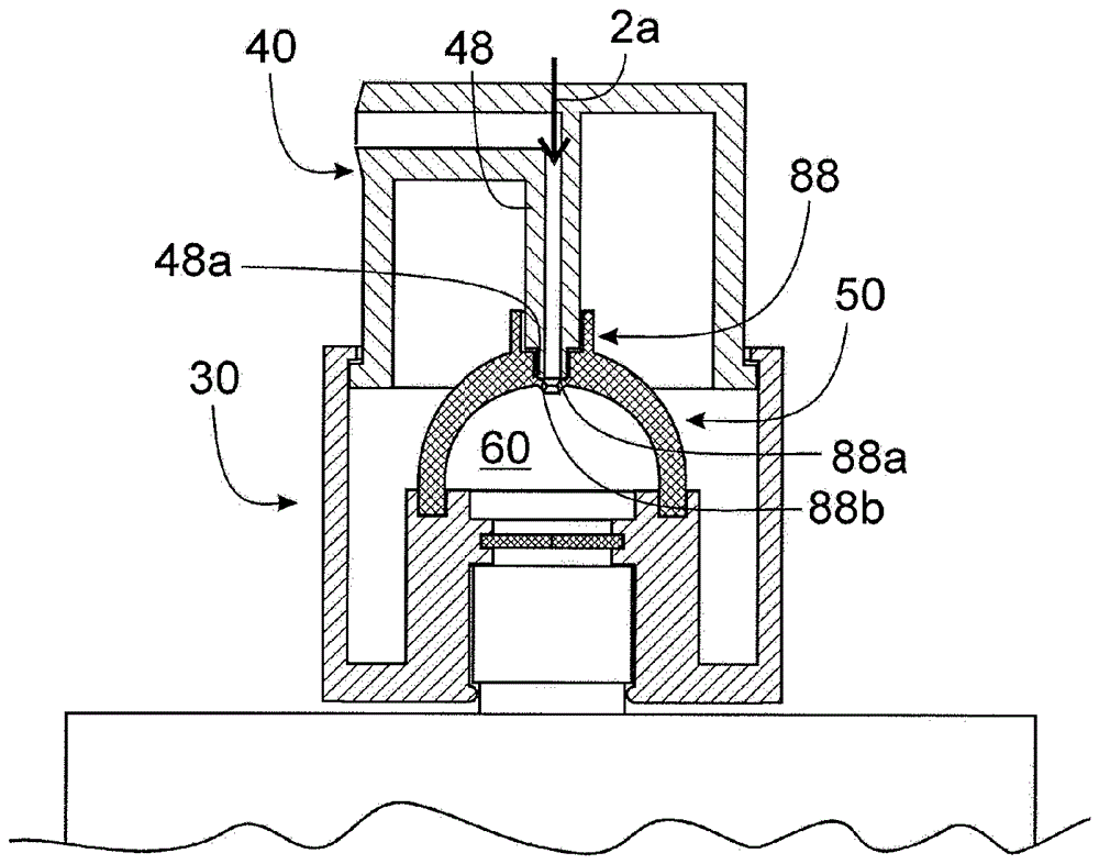
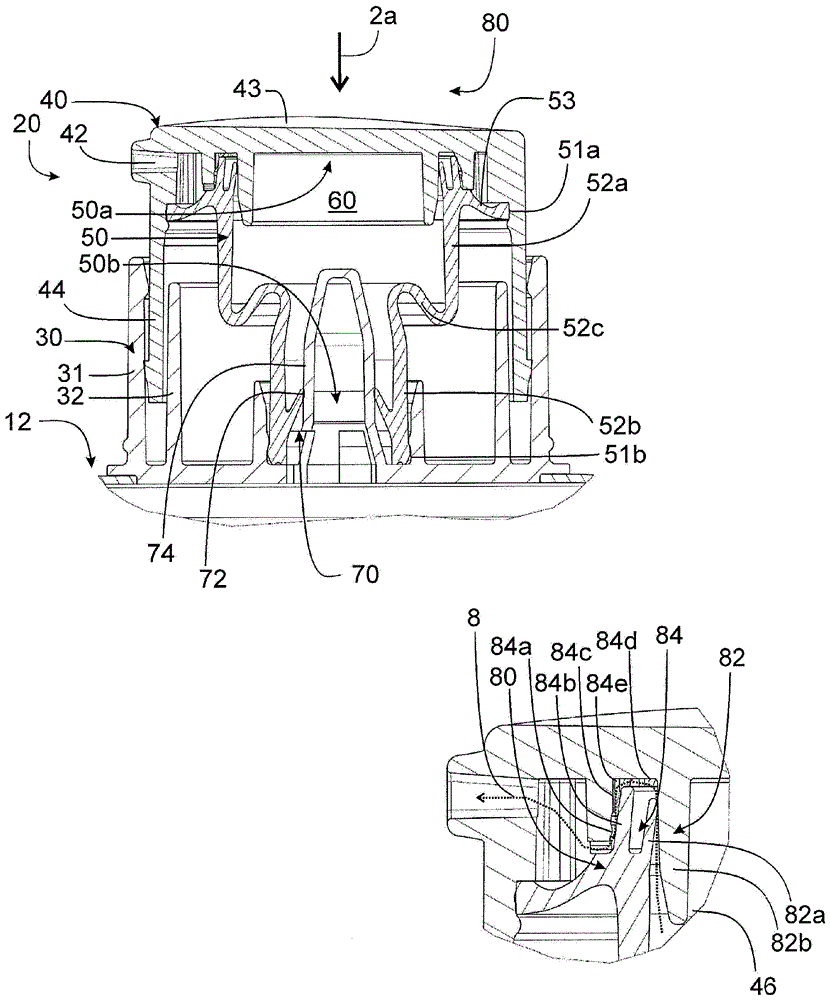
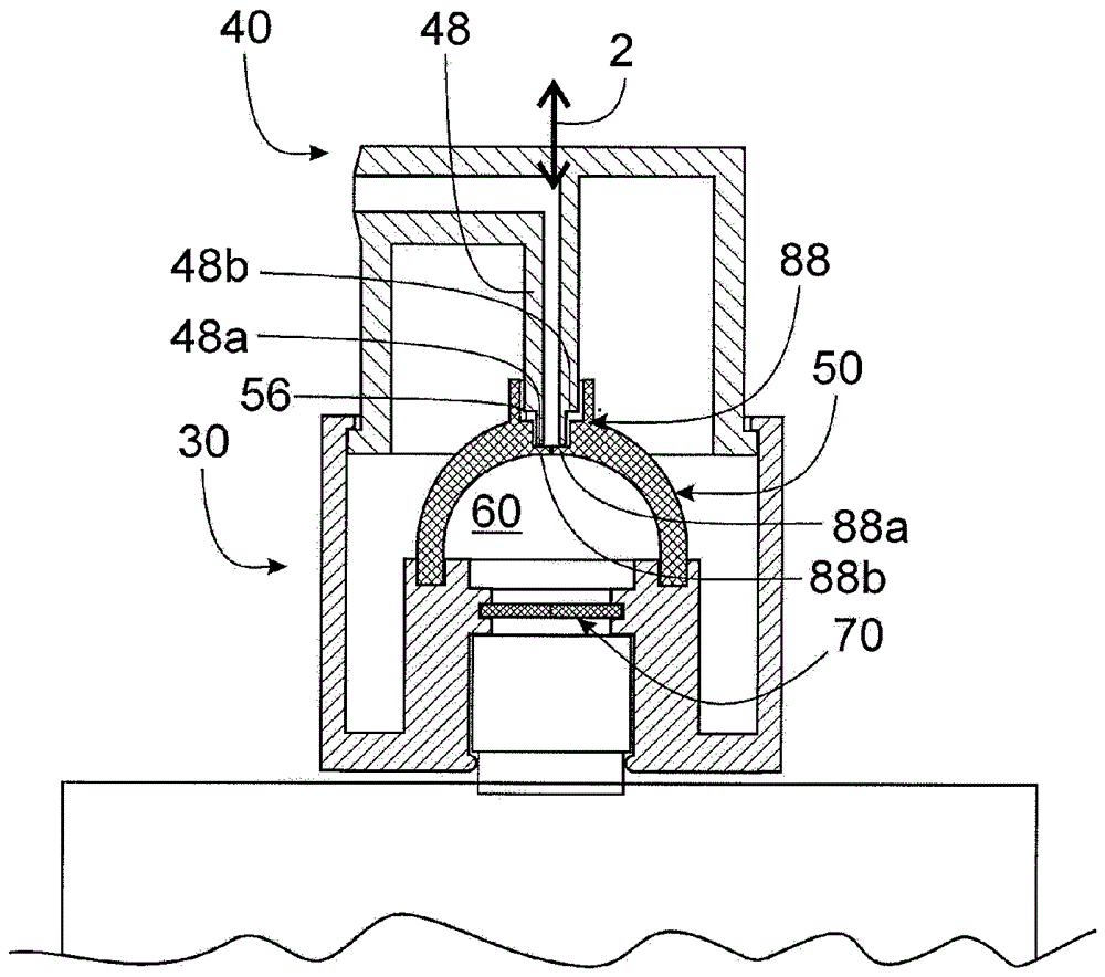
[0034] The three subsequently described embodiments present liquid dispensers that can have different kinds of liquid reservoirs. Since the embodiment according to the invention is advantageous in particular when the fluid reservoir is designed as a tube, such a tubular fluid reservoir is subsequently mentioned. However, this should be understood as an example.

[0035] All three dispensers described subsequently have a discharge head which is fixed on a tube or another liquid reservoir and which has a pump chamber variable in volume which can be controlled by actuating the handle relative to the associated The displacement of the base is reduced in order to drain the liquid. The following description of the operating principle takes place on the assumption that the pump chamber is not filled with liquid, since it is provided according to the invention that the outlet valve of the pump chamber is opened regardless of the liquid pressure occurring during actuation. Obviously,...


PUM


Abstract

2. Fluid dispenser for the discharge of pharmaceutical or cosmetic fluids. 2.1 Fluid dispensers for the discharge of pharmaceutical or cosmetic fluids are known, which comprise a fluid reservoir (12), in which the fluid is stored prior to discharge, an outlet channel (42) through which the fluid can be dispensed to an environment, a pump chamber (60) which, starting from an initial state with maximum pump chamber volume, can be volumetrically reduced by a manual pump activation by means of an activation handle (40), wherein an inlet valve arrangement (70) is provided between the fluid reservoir (12) and the pump chamber (60), which valve arrangement opens in a pressure regulated manner when a negative pressure exists in the pump chamber (60) with respect to the fluid reservoir (12), and wherein an outlet valve arrangement (80) is provided between the pump chamber (60) and the discharge opening (42). 2.2 An outlet valve arrangement (80) is proposed which comprises a switching valve (84; 86; 88) that is mechanically compelled to open in reaction to a displacement of the activation handle (40) and independent of the fluid pressure in the pump chamber (60). 2.3 The use in particular for fluid dispensers with fluid reservoirs that are variable in volume.

Description

technical field [0001] The invention relates to a liquid dispenser for discharging medicinal or cosmetic liquids or liquids from the food sector. This type of liquid dispenser is equipped with a liquid reservoir (in which the liquid is stored before being discharged), an outlet channel (through which the liquid can be sent out to the environment) and a pump chamber (with a The initial state of the maximum pump chamber volume is the starting point which can be reduced in volume by manual pump actuation by means of the joystick). In this type of liquid distributor, an inlet valve assembly is arranged between the liquid reservoir and the pump chamber, which opens in a pressure-controlled manner when a negative pressure exists in the pump chamber relative to the liquid reservoir. In addition, an outlet valve assembly is arranged between the pump chamber and the outlet opening. Background technique [0002] Distributors of this type are variously known from the prior art. Thes...

Claims


Application Information

Patent Timeline
Patent Type & Authority Applications(China)
IPC IPC(8): B05B11/00
CPCB05B11/1028B05B11/1033B05B11/1036B05B11/1035B05B11/1053A45D34/04A45D2034/002A45D2200/056
Inventor T.布鲁德T.鲍曼
Owner APTAR RADOLFZELL
Why Eureka
Try Eureka