Battery pack

A technology for battery packs and battery packs, applied in secondary batteries, battery pack components, circuits, etc., can solve problems such as poor safety and economical efficiency of battery packs, inseparable battery use environments, and damage to battery packs, reaching a practical scope Wide range, reliable voltage output, and extended working life

Inactive Publication Date: 2016-10-26
浙江杜氏新能源科技有限公司
View PDF4 Cites 1 Cited by
  • Summary
  • Abstract
  • Description
  • Claims
  • Application Information

AI Technical Summary

Problems solved by technology

In addition, the current vehicle power battery may be short-circuited due to various factors during use, causing the battery pack to burn out. Since the batteries in the battery pack are connected together, when a short circuit occurs in one place, the excessive current May cause damage to the entire battery pack, making the battery pack poor in safety and economy
Moreover, the number of cycles of the battery is not only related to manufacturing factors, but also inseparable from the environment in which the battery is used.

Method used


Image

  • Battery pack
  • Battery pack
  • Battery pack

Examples


Embodiment 1

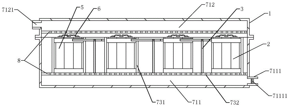
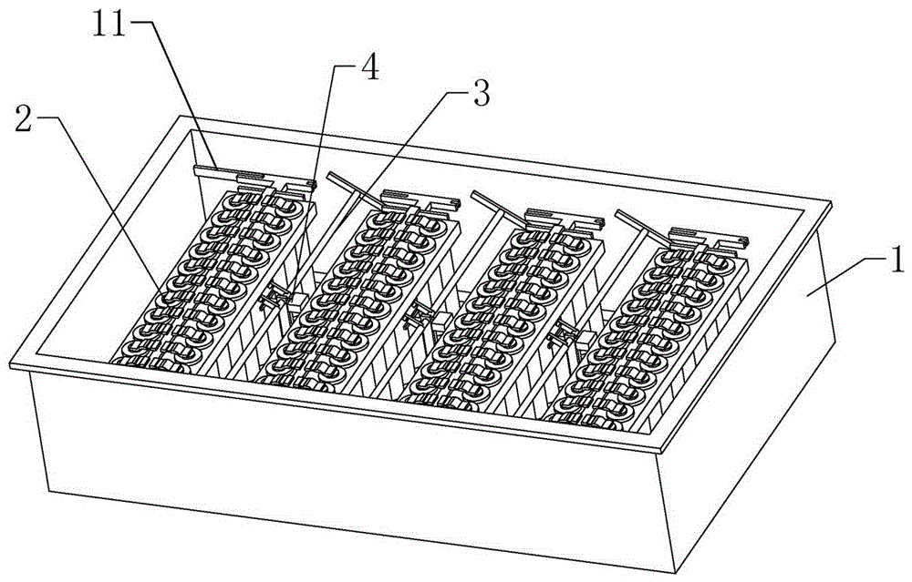
[0041] according to Figure 1 to Figure 7 As shown, a battery pack includes a battery pack case 1, a battery pack 2 in the battery pack case 1 and a battery pack bracket 8 for supporting the battery pack 2, and the number of battery packs 2 in the battery pack case 1 is divided into two groups As mentioned above, the battery pack casing 1 is also provided with a temperature control device 7, and the battery pack 2 includes the first terminal post 21 and the second terminal post 22 arranged at both ends of the battery pack 2, and the battery cells 5 and used to connect the battery cells 5. The safety nickel belt 6 is provided between the adjacent battery packs 2 to adjust the connecting rod 3 and the transfer block 4 of the battery pack 2, and the battery pack shell 1 is provided with a terminal 11 connected to the battery pack 2 ;

[0042]The temperature control device 7 includes a temperature sensor in the battery pack casing 1, an air induction chamber 711 and an air outlet...

Embodiment 2

[0054] The difference from the first embodiment above is that a connecting hole 6311 is provided in the connecting area 631 of the main belt, and a positioning hole 611 is provided on the main belt body 61 . 1. The connection hole 6311 and the positioning hole 611 are fixed, and the strap connection area 32 is welded and fixed to the battery cell 5. This structure allows the battery cell to be disassembled separately. When a single battery cell is damaged, it is convenient to replace the battery cell.

Embodiment 3

[0056] The difference from the above-mentioned embodiment 1 or 2 is that several through holes are provided in the protection area 33 , the cross-sectional area of ​​the protection area is reduced by setting the through holes, and the porous structure facilitates the breakage of the protection area 33 .


PUM


Abstract

The invention relates to the field of power batteries for automobiles, in particular to a battery pack which comprises a battery pack shell, more than two battery sets and a battery set support. The battery sets and the battery set support are arranged in the battery pack shell, the battery pack shell is further provided with a temperature control device, each battery pack comprises a first binding post, a second binding post, single batteries and safety nickel strips, each first binding post and the corresponding second binding post are arranged at two ends of the corresponding battery set, switchover rods and switchover blocks are arranged among the adjacent battery sets, and wiring terminals which are connected with the battery sets are arranged in the battery pack shell; the temperature control device comprises temperature sensors, an induced air cavity and an air outlet cavity, the temperature sensors are arranged in the battery pack shell, the induced air cavity and the air outlet cavity are arranged between the battery set support and the battery pack shell, an air inlet which is connected with the induced air cavity is formed in the induced air cavity, an exhaust port is arranged on the air outlet cavity, the battery set support is provided with heater plates which are clamped among the battery sets, and ventilation openings are formed in the battery set support.

Description

technical field [0001] The invention relates to the field of automotive power batteries, in particular to a battery pack. Background technique [0002] As a new energy vehicle, electric vehicles have been widely promoted at present, and lithium-ion batteries have the advantages of small size, light weight, and no pollution to the environment, so battery packs composed of lithium-ion batteries are widely used in electric vehicle power batteries . For power batteries for electric vehicles, power batteries must meet the four requirements of high specific energy, high specific power, long life, and high safety, as well as the requirements for battery packs, so as to meet the needs of contemporary consumers for power vehicles. [0003] At present, cars usually use battery packs with designed rated voltages to assemble them in the car. However, different types of cars require different output voltages. As a result, the production of battery packs needs to be composed of battery p...

Claims


Application Information

Patent Timeline
Patent Type & Authority Applications(China)
IPC IPC(8): H01M2/10H01M10/42H01M10/48H01M10/617H01M10/625H01M10/637H01M10/6554H01M10/6562H01M50/249
CPCH01M10/42H01M10/486H01M10/617H01M10/625H01M10/637H01M10/6554H01M10/6562H01M50/20Y02E60/10
Inventor 杜永庆宋建新郭颖李俊
Owner 浙江杜氏新能源科技有限公司
Why Eureka
Try Eureka