


Quick Research
Generate reliable direction feasibility study reports for your R&D in just a few steps.

Technical Q&A
Discover and master advanced knowledge NOW. Basics, ideas, possibilities, all at once.

Find Solutions
As an expert in R&D theories, this can generate solutions to your technical problems instantly.

Evaluate Feasibility
Analyze your overall solution with one click, know your potential R&D risks in advance.

Monitor Landscape
Get weekly tech updates, stay abreast of the latest tech innovations and key insights.
A laser module of a line throwing instrument and a laser line throwing instrument
A technology of laser modules and line throwing instruments, which is applied in the direction of instruments, measuring instruments, active optical measuring devices, etc., can solve the problems of high equipment cost, difficulty in adjusting the line throwing angle, and high power consumption, so as to save costs and effectively Conducive to the effect of miniaturization design
- Summary
- Abstract
- Description
- Claims
- Application Information
AI Technical Summary
Problems solved by technology
Method used
Image

Examples
Embodiment 1
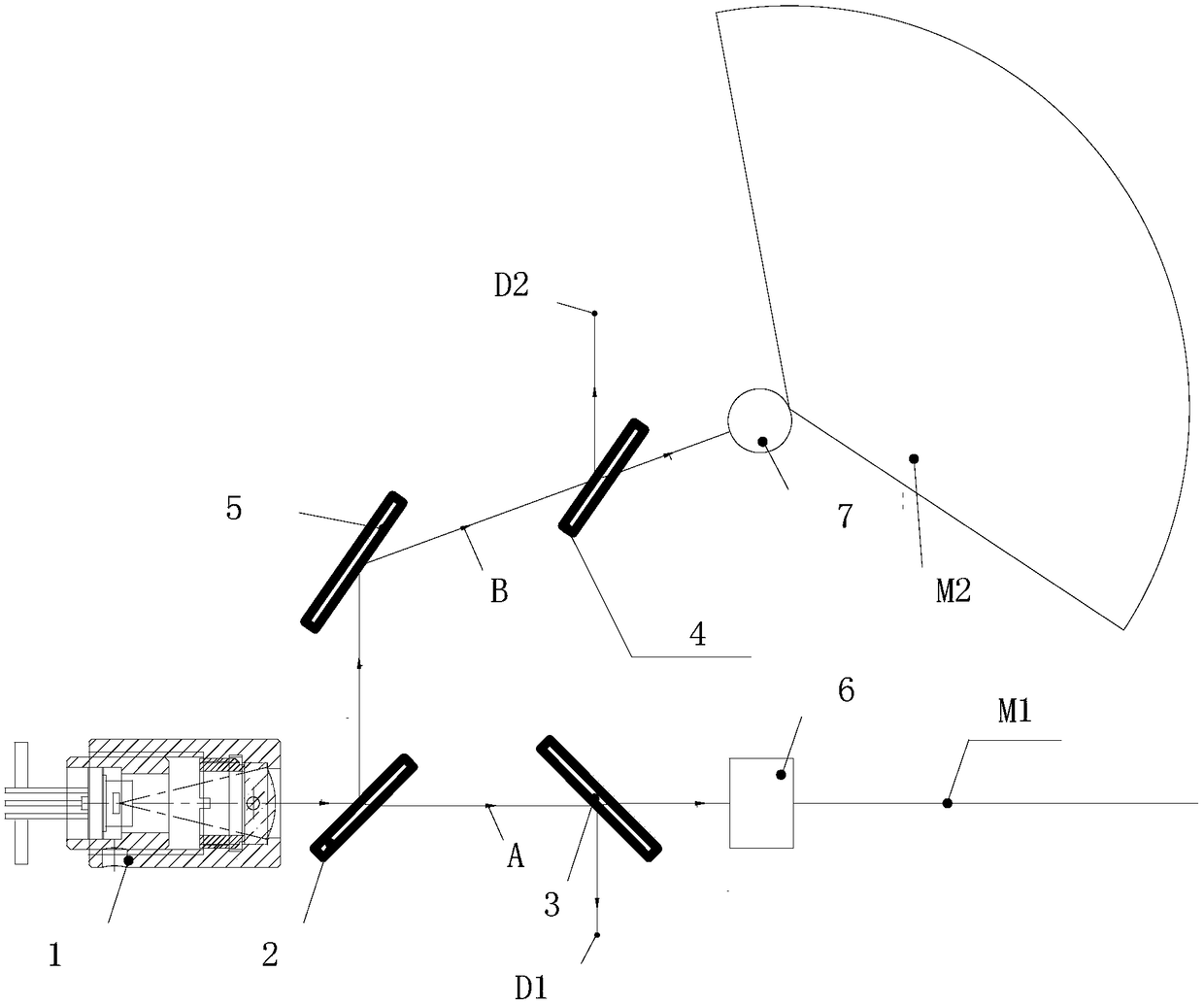
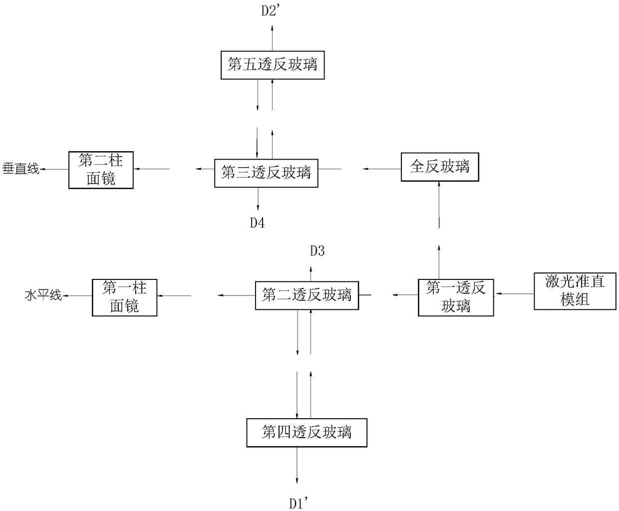
[0029] Such as figure 1 As shown, the laser module of the line projector provided in this embodiment includes a light source assembly and an optical path assembly, wherein the light source assembly includes a laser collimation module 1, and the optical path assembly includes a first transflective glass 2, a second transflective Glass 3 , third transflective glass 4 , full-reflective glass 5 , first cylindrical mirror 6 and second cylindrical mirror 7 .
[0030] In this embodiment, the laser collimation module 1, the first transflective glass 2, the second transflective glass 3 and the first cylindrical mirror 6 are arranged in a straight line, and are all located on the first straight line A, while the full reflective glass, The third transflective glass and the second cylindrical mirror are arranged in a straight line, both located on the second straight line B; wherein, the laser collimation module 1 is located on the left side of the first transflective glass 2, and the sec...
Embodiment 2
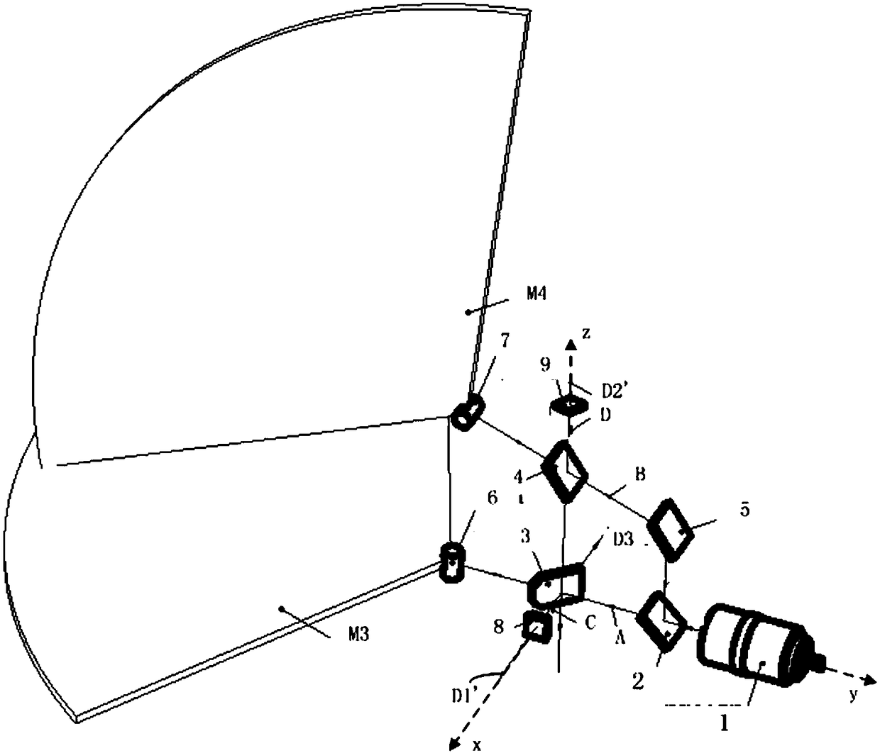
[0039] Such as figure 2 As shown, in this embodiment, in addition to the optical path components in Embodiment 1, the optical path assembly also includes a fourth transflective glass 8, and the fourth transflective glass 8 and the second transflective glass 3 are located on the third straight line C . The positions and arrangement angles of the fourth transflective glass 8 and the second transflective glass 3 are such that: the first point light is projected onto the fourth transflective glass 8, and the light part projected onto the fourth transflective glass 8 directly passes through the fourth transflective glass 8. The reflective glass 8 penetrates the second transflective glass 3 after partial reflection to form a third point of light. Wherein, in this embodiment, the first straight line is located in the y-axis direction, and the second transflective glass is set to form an angle of 45 degrees with the vertical plane (here, the plane formed by the x-axis and z-axis in ...
Embodiment 3
[0043] See you again figure 2 , the optical path assembly in this embodiment also includes a fifth transflective glass 9, the fifth transflective glass 9 and the third transflective glass 4 are on the fourth straight line D, the fifth transflective glass 9 and the third transflective glass 4 The position and arrangement angle are such that: after the second point of light is projected onto the fifth transflective glass 9, part of the light projected to the fifth transflective glass 9 directly penetrates the fifth transflective glass 9, and the other part is absorbed by the fifth transflective glass 9. Glass 9 is reflected and penetrates the third transflective glass 4 to form the fourth point of light.
[0044] Specifically, the fourth straight line D in this embodiment is a vertical straight line, and the third transflective glass 4 forms an angle with the horizontal plane, so that it can transmit a part of the light and project it onto the second cylindrical mirror 7, and ...
PUM
 Abstract
Description
Claims
Application Information
 - R&D Engineer
- R&D Manager
- IP Professional
- Industry Leading Data Capabilities
- Powerful AI technology
- Patent DNA Extraction
Browse by: Latest US Patents, China's latest patents, Technical Efficacy Thesaurus, Application Domain, Technology Topic, Popular Technical Reports.
© 2024 PatSnap. All rights reserved.Legal|Privacy policy|Modern Slavery Act Transparency Statement|Sitemap|About US| Contact US: help@patsnap.com