Quick Connector
A fast, dismantling connection technology, applied in the direction of pipes/pipe joints/fittings, branch pipelines, pipes, etc., can solve the problems of complicated and time-consuming construction process, and achieve the effect of not easy to leak, eliminate pipe diameter errors, and tightly bonded
- Summary
- Abstract
- Description
- Claims
- Application Information
AI Technical Summary
Problems solved by technology
Method used
Image

Examples
Embodiment 1
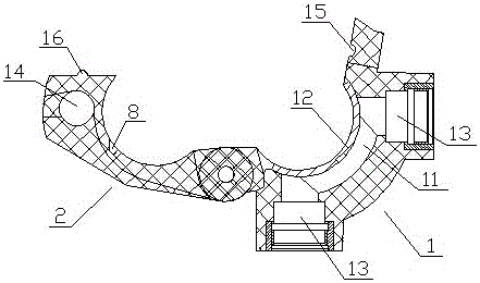
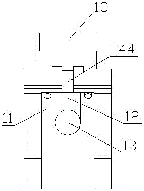
[0036] Such as Figure 1-5 As shown, a quick connector includes a main body A, the inside of the main body A is cylindrical, and the diameter of the cylinder is 40 mm; the main body A includes an upper clamping block 1 and a lower clamping block 2 . The upper block 1 is provided with a diversion groove 11, a sealing ring 12 and a joint 13, the sealing ring 12 is arranged around the diversion groove 11, a ring of protrusions 121 is provided on the sealing ring 12, and there are two joints 13, which are respectively arranged on Both ends of the diversion groove 11 are connected with the diversion groove 11, and the joint 13 is provided with threads.
[0037] One side of the upper block 1 and the lower block 2 is movably connected by a hinge, and the other side is connected by a detachable connection structure 14; the detachable connection structure 14 includes a cylindrical nut 141, a screw 142, a washer 143 and a screw threaded on the side. The opening 144 for the screw 142 to...
Embodiment 2
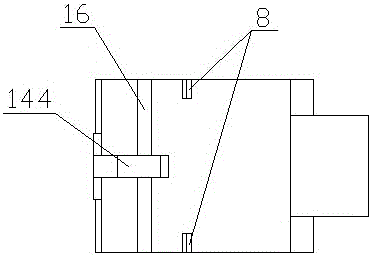
[0039] Such as Figure 1-4 , Figure 6-11 As shown, a quick connector includes a main body A, the inside of the main body A is cylindrical, and the diameter of the cylinder is 40 mm; the main body A includes an upper clamping block 1 and a lower clamping block 2 . The upper block 1 is provided with a diversion groove 11, a sealing ring 12 and a joint 13, the sealing ring 12 is arranged around the diversion groove 11, a ring of protrusions 121 is provided on the sealing ring 12, and there are two joints 13, which are respectively arranged on Both ends of the diversion groove 11 are connected with the diversion groove 11, and the joint 13 is provided with threads.
[0040] One side of the upper block 1 and the lower block 2 is movably connected by a hinge, and the other side is connected by a detachable connection structure 14; the detachable connection structure 14 includes a cylindrical nut 141, a screw 142, a washer 143 and a screw threaded on the side. An opening 144 for t...
Embodiment 3
[0045] A quick connector includes a main body A, the inside of which is cylindrical, and the diameter of the cylindrical body is 40 mm; the main body A includes an upper clamping block 1 and a lower clamping block 2 . The upper block 1 is provided with a diversion groove 11, a sealing ring 12 and a joint 13, the sealing ring 12 is arranged around the diversion groove 11, a ring of protrusions 121 is provided on the sealing ring 12, and there are two joints 13, which are respectively arranged on Both ends of the diversion groove 11 are connected with the diversion groove 11, and the joint 13 is provided with threads.
[0046]One side of the upper block 1 and the lower block 2 are movably connected by a hinge, and the other side is connected by a detachable connection structure 14 . The detachable connection structure 14 comprises a cylindrical nut 141, a screw 142, a washer 143 and a movable opening 144 for the screw 142 on the side; the cylindrical nut 141 is arranged in the l...
PUM
 Abstract
Description
Claims
Application Information
 - R&D
- Intellectual Property
- Life Sciences
- Materials
- Tech Scout
- Unparalleled Data Quality
- Higher Quality Content
- 60% Fewer Hallucinations
Browse by: Latest US Patents, China's latest patents, Technical Efficacy Thesaurus, Application Domain, Technology Topic, Popular Technical Reports.
© 2025 PatSnap. All rights reserved.Legal|Privacy policy|Modern Slavery Act Transparency Statement|Sitemap|About US| Contact US: help@patsnap.com