
Thickness measuring device and its method for steel material in red hot state

A thickness measurement and state technology, applied in measurement devices, optical devices, instruments, etc., can solve the problems of high rejection rate, inability to dynamically measure, linear distortion of laser sensors, etc., to facilitate maintenance and installation, automation of the measurement process, and reduction of The effect of scrap rate

Inactive Publication Date: 2016-10-26
NANJING NORMAL UNIVERSITY
View PDF5 Cites 1 Cited by
  • Summary
  • Abstract
  • Description
  • Claims
  • Application Information

AI Technical Summary

Problems solved by technology

[0002] For the thickness of the steel plate in the red hot state, the existing technology cannot measure dynamically, and the thickness measurement can only be performed after the steel plate is cooled
This kind of lagging measurement will obviously cause unqualified steel plates to be unable to return to the production line for adjustment in time, resulting in a high scrap rate
[0003] Although in recent years, the principle of laser measurement can achieve the purpose of online measurement, but due to the high temperature of the steel plate, which can reach 500 ° C, such a high temperature will transfer most of the heat to the sensor, which will cause serious damage to the laser sensor when it is working. Linear distortion, which greatly affects the measurement accuracy, has led to a stagnation in the implementation of measurement solutions using laser sensors

Method used


Image

  • Thickness measuring device and its method for steel material in red hot state
  • Thickness measuring device and its method for steel material in red hot state
  • Thickness measuring device and its method for steel material in red hot state

Examples


Embodiment Construction

[0036] The present invention will be described in detail below in conjunction with the accompanying drawings and embodiments.

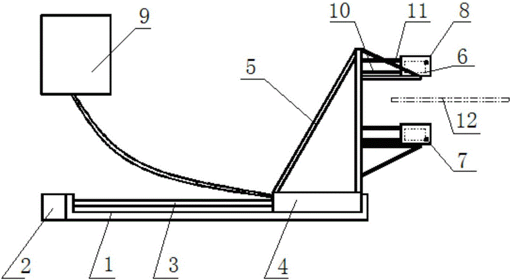
[0037] A guide rail 1 is installed on the foundation, and the stepper motor 2 is connected with the guide rail screw 3, which can drive the slider 4 to move laterally on the guide rail 1; the sensor bracket 5 is connected with the slider 4, and two incubators 8 are fixed on the sensor bracket 5 Upper, upper and lower symmetrical arrangements; water inlet pipe 10 and outlet pipe 11 are connected to incubator 8 to realize water circulation and cooling; laser displacement sensor 6 and temperature sensor 7 that can measure high-temperature objects are installed in the incubator; analyzer 9 controls the connection of power supply and The stepper motor 2 moves, and displays the measurement data and comparison results, and sends instructions in time to adjust the steel plate production line.

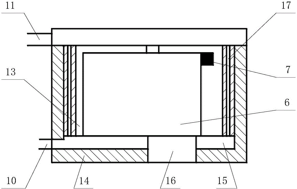
[0038] Such as figure 2 As shown, the incubator 8 includes an i...


PUM

PropertyMeasurementUnit
Thicknessaaaaaaaaaa

Abstract

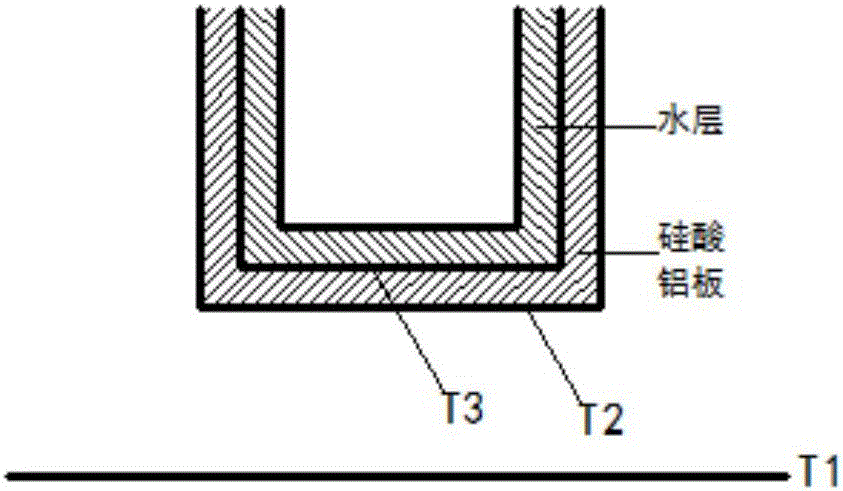
The invention provides a thickness measuring device and its method for steel material in red hot state. In the measuring device, a stepping motor is connected with a guide rail lead screw and drives slide blocks to move along the guide rail. A sensor support is connected with the slide blocks; two temperature preserving boxes are fixed on the sensor support in a symmetrical manner; each temperature preserving box is equipped with a laser displacement sensor and a temperature sensor. Each temperature preserving box comprises an inner cavity, a heat insulating layer, a water cooling layer, a probing window, a water cooling channel, a water inlet pipe, a water outlet pipe. The water cooling layer is arranged at the external part of the inner cavity of the temperature preserving box; the heat insulating layer is arranged at the external part of the water cooling layer; the water cooling layer is communicated respectively with the water inlet pipe and the water outlet pipe. An analyzer is respectively connected with the laser displacement sensors, the temperature sensors and the stepping motor. The device of the invention can realize the measurement of the thickness of a steel plate in red hot state; the measurement process is automatic, the efficiency is high and instant, and problems with the thickness of the steel plate can be found in time, thus reducing the defect rate of steel.

Description

technical field [0001] The invention relates to a device for measuring the thickness of steel in a red-hot state and a measuring method thereof, belonging to the technical field of mechanical measurement. Background technique [0002] For the thickness of the steel plate in the red hot state, the existing technology cannot measure dynamically, and the thickness measurement can only be performed after the steel plate is cooled. This kind of hysteresis measurement will obviously cause unqualified steel plates to be unable to return to the production line for adjustment in time, resulting in a high scrap rate. [0003] Although in recent years, the principle of laser measurement can achieve the purpose of online measurement, but due to the high temperature of the steel plate, which can reach 500 ° C, such a high temperature will transfer most of the heat to the sensor, which will cause serious damage to the laser sensor when it is working. Linear distortion, which greatly affe...

Claims


Application Information

Patent Timeline
IPC IPC(8): G01B11/06
CPCG01B11/06
Inventor 魏玉敏徐文胜刘雪杰范瑞瑞李禹江
Owner NANJING NORMAL UNIVERSITY
Learn More