
Industrial robot base coordinate measuring method

A technology of industrial robots and base coordinates, which is applied in the direction of measuring devices, instruments, manipulators, etc., can solve problems such as undiscovered robot base coordinates, and achieve good application prospects

Inactive Publication Date: 2016-10-26
CHONGQING INST OF GREEN & INTELLIGENT TECH CHINESE ACADEMY OF SCI
View PDF5 Cites 33 Cited by
  • Summary
  • Abstract
  • Description
  • Claims
  • Application Information

AI Technical Summary

Problems solved by technology

[0003] At present, no discussion or patent on the measurement method of the robot base coordinate has been found, so it is particularly important to conduct research on the measurement method of the robot base coordinate

Method used


Image

  • Industrial robot base coordinate measuring method
  • Industrial robot base coordinate measuring method

Examples


Embodiment Construction

[0020] The preferred embodiments of the present invention will be described in detail below with reference to the accompanying drawings.

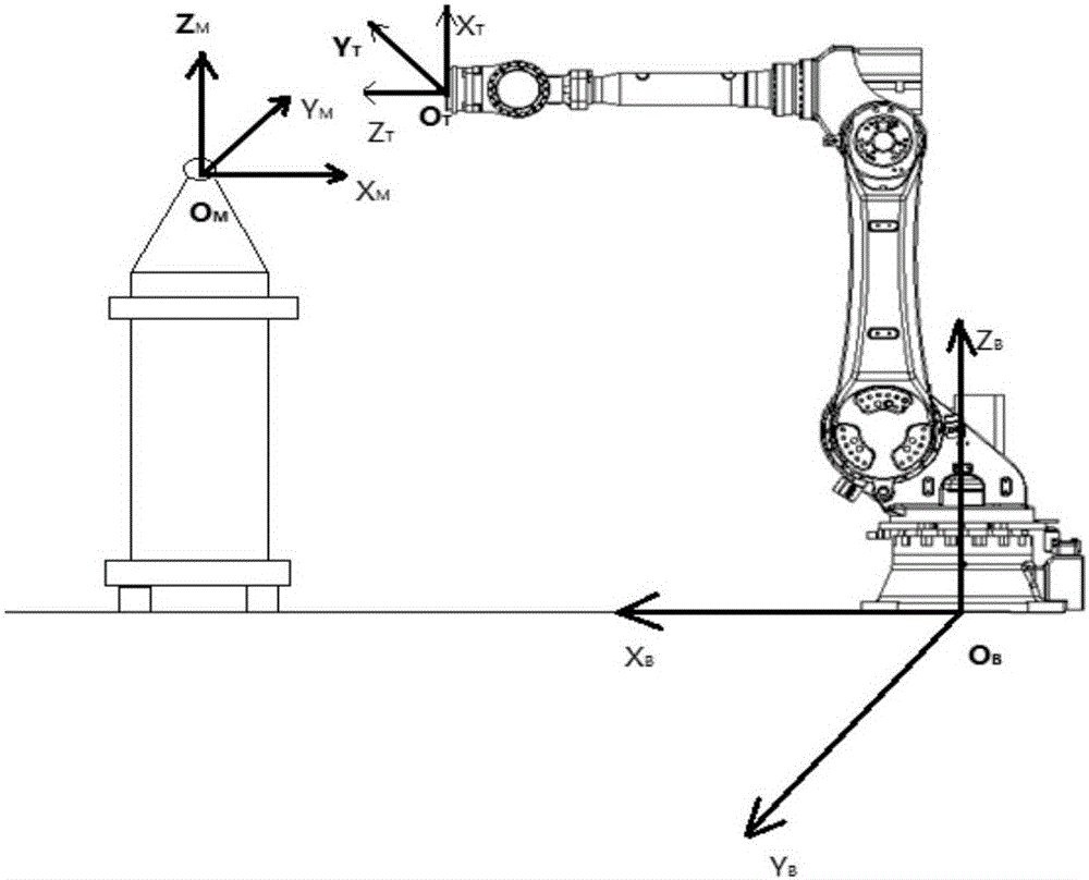
[0021] figure 1 It is a test model diagram of the test method of the present invention, and each joint of the whole robot is in the initial mode of zero point. According to the industrial robot technical indicators, the base coordinate system of the robot is located at the contact between the robot base and the bottom surface. Set the robot base coordinate system to O B x B Y B Z B , the coordinate system of the end flange of the robot is O T x T Y T Z T , the measurement coordinate system of the laser tracker is O M x M Y M Z M . Before the robot performance test, it is necessary to accurately find the position of the robot base coordinate system, and calculate the mathematical conversion relationship between the laser tracker test coordinate system and the base coordinate system.

[0022] When the joints of the robot are at ...


PUM


Abstract

The invention relates to an industrial robot base coordinate measuring method, which comprises the following steps: setting a robot base coordinate system to be OBXBYBZB, a robot tail-end flange coordinate system to be OTXTYTZT, and a measurement coordinate system carried with a laser tracker to be OMXMYMZM; arranging a target ball in the center of a flange at the tail end of a robot, and ensuring the target ball does not shift in the robot motion process; keeping other shafts of the robot immobile, only enabling a first shaft to rotate, and carrying out fitting on a plurality of point location data obtained after continuous rotation to obtain a circle, the normal vector of the circle being Z-axis direction of the base coordinate system; placing the target ball at a plurality of places in a robot base plane, measuring multiple points and obtaining a robot base plane equation through data fitting, the point obtained when the normal vector obtained through fitting in the step above meets the robot base plane being an original point OB of the base coordinate system, and thus a coordinate axis ZB can be obtained; controlling a second shaft of the robot to be in single axis motion, placing the target ball at some fixed place of the second shaft, continuously rotating for a plurality of point positions and carrying out fitting on the recorded points data to obtain a plane, projection of the plane to the base plane being the coordinate axis XB; and through a right-hand rule: ZB=XB*YB, obtaining the coordinate axis YB.

Description

technical field [0001] The invention belongs to the technical field of industrial robot performance testing and robot calibration, and relates to a method for measuring the coordinates of an industrial robot base. Background technique [0002] In the performance testing and calibration of industrial robots, it is often necessary to measure the position accuracy of the robot end: the position accuracy refers to the difference between the position of the command pose and the actual measured position cluster center. Therefore, the actual measurement value of the corresponding point must be obtained, which requires unifying the measurement coordinate system with the robot base coordinate system. The base coordinate system of the robot cannot be directly measured, but can only be obtained through indirect measurement methods. [0003] At present, no discussion or patent on the measurement method of the robot base coordinate has been found, so it is particularly important to cond...

Claims


Application Information

Patent Timeline
IPC IPC(8): G01B11/00B25J19/00
CPCB25J19/0095G01B11/002
Inventor 徐泽宇石明全王晓东冯少江
Owner CHONGQING INST OF GREEN & INTELLIGENT TECH CHINESE ACADEMY OF SCI
Learn More