A valve group for a hydraulic coupling

A technology for hydraulic couplings and valve groups, applied in valve details, valve devices, chemical instruments and methods, etc., can solve the problems that the valve body cannot be closed, the control equipment is damaged, and the rejection rate is high, so as to improve safety and stability. , Reduce processing cost, easy to remove and clean

Active Publication Date: 2018-05-01
DADAO SOFT STAR MACHINERY CO LTD
View PDF6 Cites 0 Cited by
  • Summary
  • Abstract
  • Description
  • Claims
  • Application Information

AI Technical Summary

Problems solved by technology

[0002] A valve-controlled liquid-filled hydraulic coupling is a hydraulic transmission device used to connect a power source (usually an engine or a motor) with a working machine and transmit torque by changing the liquid momentum torque. A general hydraulic coupling The working medium is water or turbine oil. The coupling must be equipped with a special valve group to control the quantitative addition of water. The existing valve group includes a liquid inlet, a liquid outlet, a valve stem piston, and a solenoid valve. Its structural design is The defect is that the control of the flow rate cannot be realized. There is no water filter device in the valve group. A 1mm hole is used for the water inlet of the piston back to the space water chamber. During normal use, the 1mm hole is often blocked by impurities in the water, causing the valve body to fail to close and damage the controlled equipment. The other 1mm The small hole processing process is complicated, the scrap rate is high, and the cost is high. The valve group has no safety valve, and the water pressure is too high, causing the inside of the coupler to be overcharged, which will damage the shaft seal and bearing inside the coupler.

Method used


Image

  • A valve group for a hydraulic coupling
  • A valve group for a hydraulic coupling
  • A valve group for a hydraulic coupling

Examples


Embodiment Construction

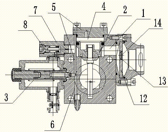
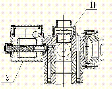
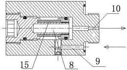
[0018] As shown in the accompanying drawing, a valve group for a hydraulic coupling includes a valve body, the valve body is provided with a liquid inlet 1, a liquid outlet, a valve stem piston 2, and a solenoid valve 3, and the valve stem piston 2 is used for on-off inlet and outlet. The waterway connected to the liquid port and the liquid outlet, the head of the valve stem piston is the backwater chamber 4, the backwater chamber 4 is connected to the return waterway 5, and the backwater way 5 controls the connection between the backwater way 5 and the signal waterway 6 through a solenoid valve, and the backwater way 5 An external filter 7 is fixedly connected with the valve body, and the external filter 7 is connected in series with the return water channel 5, and becomes a section of the filter water channel of the return channel. The external filter 7 includes an outer shell and a filter element 8, and the shell is provided with Waterway Ⅱ9, waterway Ⅲ10, one end of waterwa...


PUM


Abstract

The invention discloses a valve set for a hydraulic coupling. The valve set comprises a valve body; the valve body is provided with a liquid inlet, a liquid outlet, a valve rod piston and an electromagnetic valve; the tail part of the valve rod piston is a back water cavity; the back water cavity is communicated with a water return way; the water return way controls connection and disconnection with a signal water way through the electromagnetic valve; an external filter is arranged on the water return way for fixedly connecting with the valve body, and is serially connected to the water return way; the external filter includes an outer shell and a filter element; the shell is provided with a water way II and a water way III; one end of the water way II is connected with an inlet of the filter element, and the other end is communicated with the water return way; one end of the water way III is communicated with an outlet of the filter element, and the other end is communicated with the back water cavity through the water return way; and a flow valve assembly is arranged in a liquid inlet of the valve set. Compared with a traditional valve set of a coupling, the valve set for the hydraulic coupling changes the structure design of a piston, removes 1 m small holes in the head and tail parts of the piston, reduces the machining cost, and improves the reliability; the external filter is added in the valve body for preferably filtering impurities in water to preferably protect the piston in the valve set, to reduce the damage of the piston and to achieve longer service life; and the liquid inlet is added with the flow valve assembly for guaranteeing stable liquid filling of the coupling without exceeding the standard, so that the safety and the stability of the valve set are improved.

Description

technical field [0001] The invention relates to a valve, in particular to a valve group for a hydraulic coupling. Background technique [0002] A valve-controlled liquid-filled hydraulic coupling is a hydraulic transmission device used to connect a power source (usually an engine or a motor) with a working machine and transmit torque by changing the liquid momentum torque. A general hydraulic coupling The working medium is water or turbine oil. The coupling must be equipped with a special valve group to control the quantitative addition of water. The existing valve group includes a liquid inlet, a liquid outlet, a valve stem piston, and a solenoid valve. Its structural design is The defect is that the control of the flow rate cannot be realized. There is no water filter device in the valve group. A 1mm hole is used for the water inlet of the piston back to the space water chamber. During normal use, the 1mm hole is often blocked by impurities in the water, causing the valve...

Claims


Application Information

Patent Timeline
Patent Type & Authority Patents(China)
IPC IPC(8): F16K13/00F16K31/06B01D35/04
CPCB01D35/04F16K13/00F16K31/06
Inventor 韩石全
Owner DADAO SOFT STAR MACHINERY CO LTD
Why Eureka
Try Eureka