
Gas plug valve

A technology for gas cock valves and valve stems, which is applied to cocks including cut-off devices, valve details, valve devices, etc. It can solve the problems of large gas volume, explosive sound, difficult multi-level flow control, etc., and achieve the goal of reducing gas output. Effect

Active Publication Date: 2016-10-26
ZHEJIANG XINTAO ELECTRONICS MACHINERY
View PDF12 Cites 8 Cited by
  • Summary
  • Abstract
  • Description
  • Claims
  • Application Information

AI Technical Summary

Problems solved by technology

[0006] The Chinese patent document with the publication number CN 201925516 U discloses a plug valve with multiple flow rates, which consists of a valve body and a rotatable valve core installed in the valve body. There are several flow control holes connecting the axial holes on the circumference of the valve core, and one air outlet hole corresponding to the flow control hole is set on the valve body, which overcomes the rotation of the gas flow of the existing cock valve. The disadvantage that the angle is concentrated in a very small angle range, especially when other power devices such as micro motors are used to replace the flow adjustment of the plug valve manually, it is difficult to realize the disadvantage of multi-level flow control in a very small angle range, The user can easily adjust the gas flow of the gas stove to obtain multiple levels of firepower
[0007] In the prior art, when the valve stem is pressed down to ignite, the gas enters the gas distribution chamber of the valve core, and the inner and outer rings of the cooker both emit gas with a large amount of gas. Once the ignition is unsuccessful, it will produce a detonation

Method used


Image

  • Gas plug valve
  • Gas plug valve

Examples


Embodiment Construction

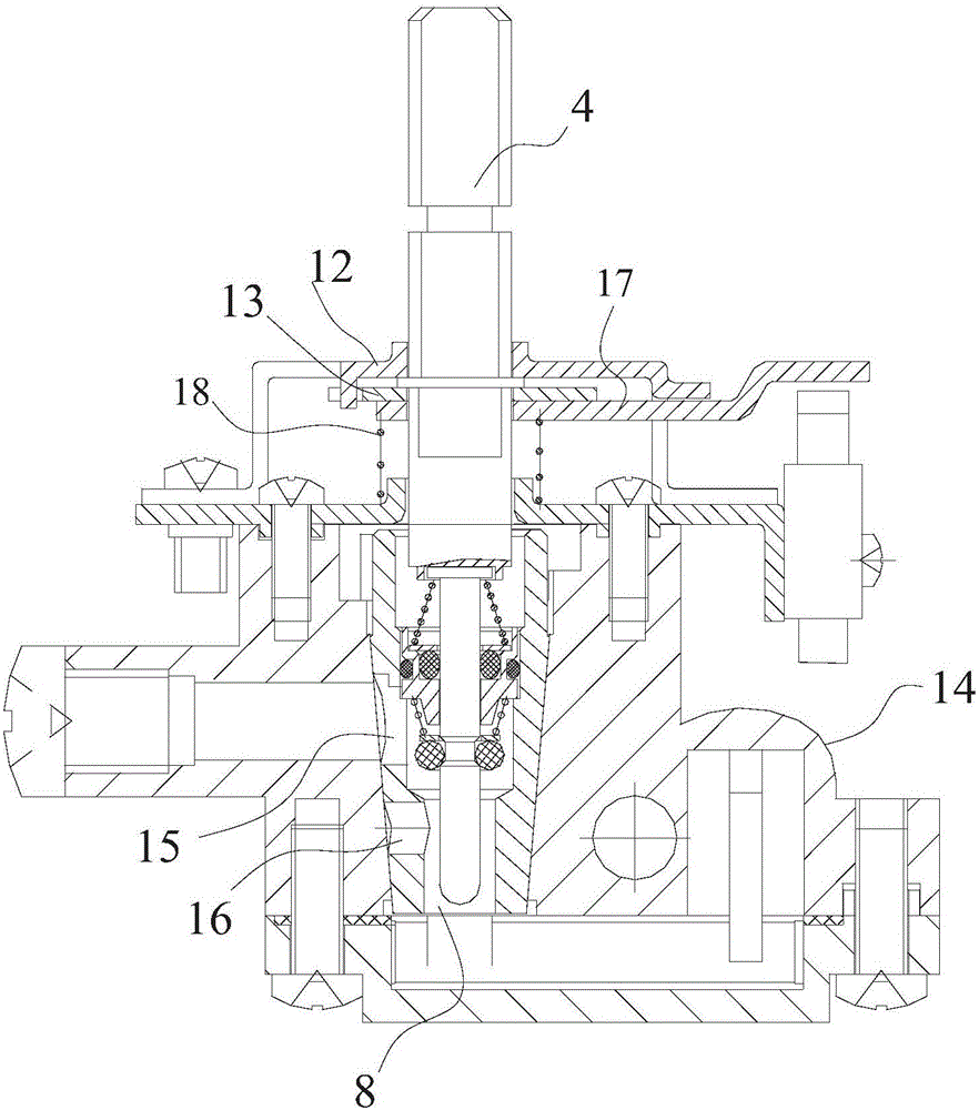
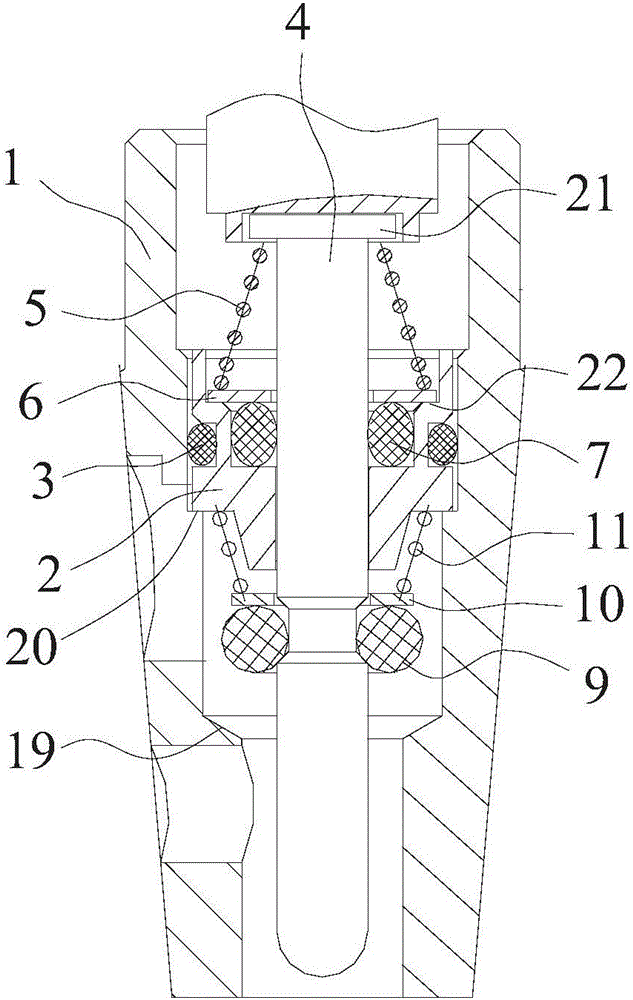
[0031] see figure 1 , figure 2 , a gas cock valve in this embodiment, including a valve body 14, a valve core 1 is fitted in rotation in the valve body 14, the valve core 1 is a hollow structure, the inside is a gas distribution chamber, and the inner axial bottom end of the valve core 1 is an inlet The air hole 8 is provided with an air supply solenoid valve matched with the air inlet 8 in the valve body, and the side wall of the valve body 14 is provided with an outer ring air supply hole 15 and an inner ring air supply hole 16 .

[0032] A valve stem 4 is inserted inside the valve core 1, and the valve stem 4 can be rotated so that the outer ring air supply hole 15 and the inner ring air supply hole 16 correspond to the corresponding air holes on the valve body. In order to ignite, the valve stem 4 can also move axially , the valve stem 4 is provided with a fixed plate 13, and the valve body 14 is provided with a limiting plate 12 for blocking the fixed plate 13, only whe...


PUM


Abstract

The invention discloses a gas plug valve. The gas plug valve comprises a valve core with a gas distribution cavity; a valve rod driving the valve core to rotate is inserted into one axial end of the gas distribution cavity and can be axially moved relative to the valve core and pressed down for realizing ignition; an air inlet is formed in the other axial end of the gas distribution cavity, an inner ring gas supply hole and an outer ring gas supply hole both communicating with the gas distribution cavity are sequentially formed in the side wall of the valve core in the axial direction, and an annular table located between the inner ring gas supply hole and the outer ring gas supply hole is arranged on the inner wall of the gas distribution cavity; and the valve rod is provided with seal washers abutting against the annular table in the pressed-down ignition mode, and the one, away from the gas inlet hole, of the inner ring gas supply hole and the outer ring gas supply hole and the gas inlet hole are blocked by the seal washers and do not communicate with each other in the pressed-down ignition mode. According to the gas plug valve, one of the inner ring gas supply hole and the outer ring gas supply hole and the gas inlet hole are blocked by the seal washers and do not communicate with each other when the valve rod is pressed down for ignition, the total gas output quantity is reduced, and detonation does not occur even if ignition does not succeed.

Description

technical field [0001] The invention relates to a valve, in particular to a gas cock valve. Background technique [0002] Today's household appliances such as water heaters and gas stoves all use pipeline gas or liquefied gas as fuel. Compared with electric heating, combustion heating of pipeline gas or liquefied gas has higher thermal efficiency and faster heating rate, so it is more popular with the public. The heating temperature adjustment of ordinary electrical appliances is relatively simple, only need to adjust the working power of the electrical appliances, but for electrical appliances using gas, it is necessary to adjust the intake air volume, and the main part of the intake air volume adjustment is the gas cock valve. [0003] The gas cock valve generally includes a valve body and a valve core. There is an air outlet on the valve core, and an air outlet is provided in the valve body. During the rotation of the valve core, the air outlet will be aligned with the ai...

Claims


Application Information

Patent Timeline
IPC IPC(8): F16K5/02F16K5/08F16K5/10F16K41/06F24C3/10F24C3/12
CPCF16K5/0207F16K5/0285F16K5/08F16K5/103F24C3/10F24C3/126
Inventor 张伟国潘赛斌梁圣佶章永钏梁壵壵
Owner ZHEJIANG XINTAO ELECTRONICS MACHINERY
Learn More