Exhaust gas device for separation of exhaust strokes of internal combustion engine with at least two cylinder groups

A technology for cylinder banks and internal combustion engines, which can be used in exhaust devices, internal combustion piston engines, noise reduction devices, etc., and can solve problems such as limiting the working capacity of internal combustion engines

Active Publication Date: 2016-10-26
VOLKSWAGEN AG
View PDF7 Cites 1 Cited by
  • Summary
  • Abstract
  • Description
  • Claims
  • Application Information

AI Technical Summary

Problems solved by technology

Crosstalk between the exhaust gas flows of different cylinder banks can lead to an increased residual gas content and thus to an increased tendency to knock especially in full load operation
This will limit the working capacity of the internal combustion engine

Method used


Image

  • Exhaust gas device for separation of exhaust strokes of internal combustion engine with at least two cylinder groups
  • Exhaust gas device for separation of exhaust strokes of internal combustion engine with at least two cylinder groups
  • Exhaust gas device for separation of exhaust strokes of internal combustion engine with at least two cylinder groups

Examples


Embodiment Construction

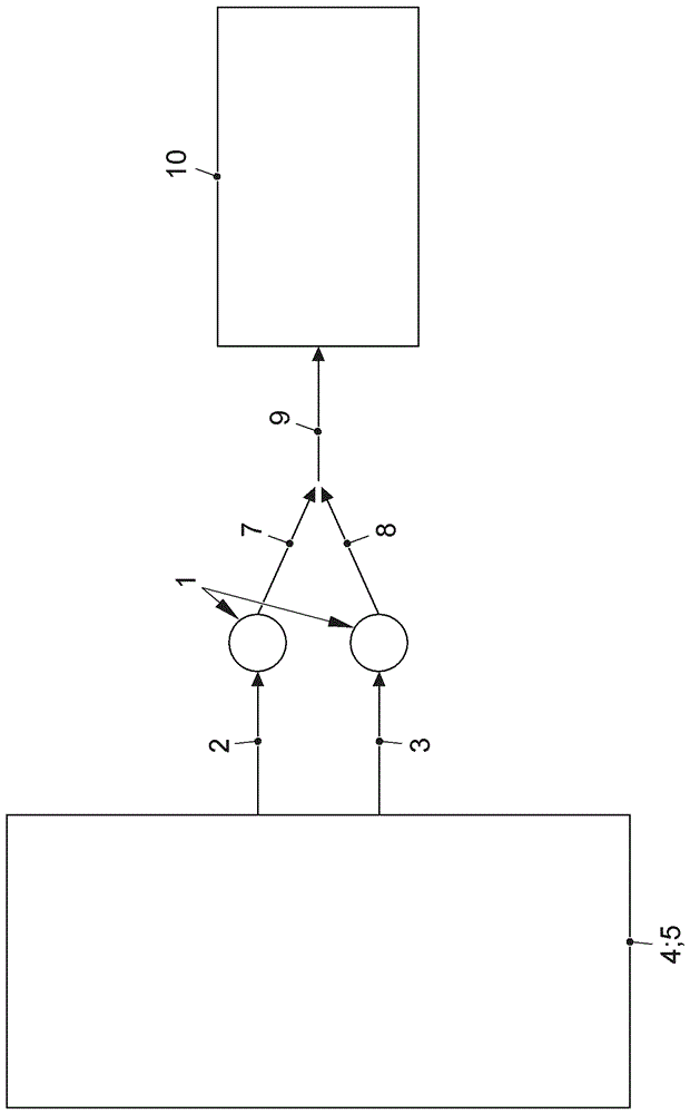
[0063] exist figure 1 and 2 The exhaust gas system 1 for separating the exhaust gas flows 2 , 3 of an internal combustion engine 4 is shown very schematically in FIG. The internal combustion engine 4 has a cylinder head 5 with an exhaust manifold (not shown in detail). The internal combustion engine 4 can have, for example, four cylinders, namely a first, second, third and fourth cylinder. The exhaust gas of the first and fourth cylinder is conducted via the exhaust gas flow 2 and the exhaust gas of the second and third cylinder is conducted via the exhaust gas flow 3 .

[0064] The internal combustion engine 4 thus has two cylinder banks, namely a first cylinder bank with the first and fourth cylinders and a second cylinder bank with the second and third cylinders. In alternative configurations it is conceivable for internal combustion engine 4 to have more than two cylinder banks, ie three or four cylinder banks. Each cylinder bank has at least one cylinder. The cylinde...


PUM


Abstract

The present invention relates to an exhaust gas device for separation of exhaust strokes of an internal combustion engine with at least two cylinder groups, wherein each of the cylinder groups is associated with an exhaust gas flow section (2, 3) which can be alternatively connected to an exhaust system (7, 8, 9) on at least one output side by means of a separator assembly (6). The crosstalk between the exhaust gas flow sections (2, 3) of the different cylinder groups is thereby reduced, i.e. adjacent cylinders in the firing sequence are associated with different cylinder groups, wherein the separator assembly (6) can operate according to the exhaust valve control time of the cylinder groups, wherein the cylinder group which discharges exhaust gas is connected to the exhaust gas flow (7, 8) on the output side through the separator assembly (6), and wherein the cylinder group which do not discharge exhaust gas is separated from the exhaust system (7, 8) on the output side through the separator assembly (6).

Description

technical field [0001] The invention relates to an exhaust system for separating the exhaust gas flow of an internal combustion engine having at least two cylinder banks, having the features of the preamble of claim 1 . [0002] Furthermore, the invention relates to a method having the features of the preamble of claim 11 . Background technique [0003] From such document DE 102 36 732 A1 a multi-flow exhaust system for separating the exhaust gas flow of an internal combustion engine is known. The internal combustion engine has at least two cylinder banks, wherein an exhaust gas flow is associated with each cylinder bank. The exhaust gas flow section leads into a switching device in the form of a bulkhead assembly, wherein the exhaust gas flow section can alternately be connected to different output-side exhaust systems by means of the bulkhead assembly. The outlet-side exhaust trains are each associated with one of the exhaust gas flows. The exhaust gas flow or the exhau...

Claims


Application Information

Patent Timeline
Patent Type & Authority Applications(China)
IPC IPC(8): F02D9/08F01N13/10F01N13/08F02D9/16F02D9/14
CPCF01N13/08F01N13/10F02D9/08F02D9/14F02D9/16F01N13/105F01N13/107F01N2240/14F01N2240/36F01N2290/02F01N2290/06F01N2290/08F02B37/00F02D23/00Y02T10/12
Inventor M.普罗维尔P.卡韦尔克
Owner VOLKSWAGEN AG
Why Eureka
Try Eureka