Down-hole gas lift valve

A technology of gas lift valve and air bag, which is applied in the direction of wellbore/well valve device, wellbore/well components, production fluid, etc., which can solve the problems of reduced oil production efficiency, accelerated oil pumping efficiency, and decline, and achieve increased Large contact area, improved flexibility, and reduced damage rate

Inactive Publication Date: 2016-10-26
CHENGDU NORTH OIL EXPLORATION DEV TECH
View PDF5 Cites 1 Cited by
  • Summary
  • Abstract
  • Description
  • Claims
  • Application Information

AI Technical Summary

Problems solved by technology

Aiming at the problem that the inaccurate adjustment of high-pressure airflow leads to the reduction of oil production efficiency in gas lift production in the prior art, the inventors set up different cavities to carry out linkage control on high-pressure airflow, so that the high-pressure airflow is between the casing and the oil pipe. The circulation is smoother, the adjustment is more precise, and the efficiency of gas lift oil recovery is improved; when in use, multiple shells are set in the annular part of the casing and the tubing, at this time the transition chamber is connected with the inside of the tubing, and the gas inlet chamber is connected to the inside of the tubing. The transition chamber is sealed off, and the return spring is in a stretched state. A large amount of high-pressure airflow is injected into the casing. The high-pressure airflow enters the air intake chamber through the communication hole. When the air intake chamber is filled, the high-pressure airflow passes through the ventilation The hole enters the adjustment chamber, and the space in the adjustment chamber is filled by the expanded air bag. The air bag is deformed and its volume is reduced by the injection of high-pressure airflow to the lower pressure of the ejector rod. The pressure decreases, and under the return force of the return spring, the ejector rod moves up, and at the same time drives the first ball to cancel the seal on the small hole, and the high-pressure airflow in the intake chamber is released through the small hole to quickly pass through the transition chamber After entering the oil pipe, the high-pressure airflow partially offsets the gravity of the oil in the oil pipe, and the lift required for the oil in the oil pipe to rise is greatly reduced, which speeds up the pumping efficiency of the oil in the oil pipe

Method used


Image

  • Down-hole gas lift valve
  • Down-hole gas lift valve

Examples


Embodiment 1

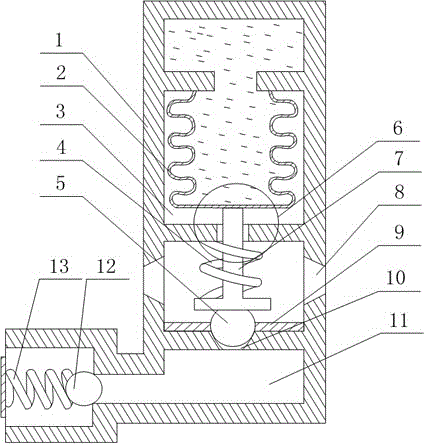
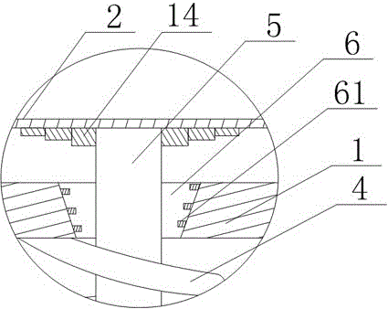
[0022] Such as figure 1 and figure 2 As shown, this embodiment includes a housing 1, in which a regulating chamber 3, an air intake chamber and a transition chamber 11 are sequentially opened from top to bottom, and the regulating chamber 3 is installed with a cylinder filled with compressed air. The airbag 2, and the adjustment chamber 3 communicate with the air intake chamber through the vent hole 6, the aperture of the vent hole 6 decreases downward along the axis of the push rod 7, and a spiral protrusion is installed on the inner wall of the vent hole 6 and along its axial direction 61, the air intake chamber communicates with the transition chamber 11 through the small hole 10, the transition chamber 11 communicates with the oil pipe, there are communication holes 8 on both sides of the air intake chamber, and a T is set in the middle of the air intake chamber type ejector rod 7, the return spring 4 is sleeved on the vertical section of the ejector rod 7, and the top o...


PUM


Abstract

The invention discloses a down-hole gas lift valve which comprises a shell. The shell is internally provided with a regulating cavity, an air inlet cavity and a transition cavity. An air bag is mounted in the regulating cavity which communicates with the air inlet cavity through an air hole, and the air inlet cavity communicates with the transition cavity through a small hole. Communication holes are formed in the two sides of the air inlet cavity, and an ejector rod is arranged in the middle of the air inlet cavity. The vertical section of the ejector rod is sleeved with a return spring, and the top of the vertical section of the ejector rod penetrates through the air hole and then extends upwards to be connected with the bottom of the air bag. A first ball is arranged at the bottom of the horizontal section of the ejector rod. A gasket is arranged on the inner wall of the air inlet cavity, and a sealing hole coaxial with the small hole is formed in the middle of the gasket. In order to solve the problem that during gas-lift oil extraction in the prior art, the oil extraction efficiency is lowered due to inaccurate adjustment of high-pressure airflow, the different cavities are arranged so as to achieve linkage control over the high-pressure airflow, the high-pressure airflow is made to flow between a casing and an oil tube more smoothly, adjustment is more accurate, and thus gas-life oil extraction efficiency is improved.

Description

technical field [0001] The invention relates to the field of oil exploitation, in particular to a downhole gas lift valve. Background technique [0002] The use of air pressure lift is the most economical oil recovery method in the modern oil production process. Gas lift can not be limited by the depth of the oil well. The injected gas can go deep into the liquid through the gas lift valves at all levels from top to bottom, so that the bottom of the tubing The weight of the liquid becomes lighter and reduces the back pressure on the oil layer, thus ensuring the smooth and continuous production of the oil well. However, during the use of the existing gas lift valve, the sphere continuously reciprocates under the strong impetus of the high-pressure airflow, that is, the sphere and the ball seat collide with each other uninterruptedly, resulting in a decrease in the airtightness of the sphere. The adjustment flexibility of the gas lift valve to the oil in the tubing is reduced...

Claims


Application Information

Patent Timeline
IPC IPC(8): E21B43/12E21B34/08
CPCE21B43/123E21B34/08
Inventor 何巍徐兵邓勇柳世成张艺久欧阳静芸
Owner CHENGDU NORTH OIL EXPLORATION DEV TECH
Why Eureka
Try Eureka