Laser cutting machine and energy control system of laser cutting multilayer composite material

A multi-layer composite material and energy control technology, applied in laser welding equipment, manufacturing tools, welding equipment, etc., can solve problems such as discontinuity, traces, control errors, etc., to improve cutting quality, reduce control errors, overcoming the effect of closure

Active Publication Date: 2016-10-26
深圳市德堡数控技术有限公司
View PDF6 Cites 6 Cited by
  • Summary
  • Abstract
  • Description
  • Claims
  • Application Information

AI Technical Summary

Problems solved by technology

[0007] However, in the former instruction control mode, because the mechanical part of the laser cutting machine has a certain lag in the execution of the control system instructions, it will cause control errors, which may cause traces on the underlying material, or cause graphic elements to be damaged. The cutting of the corners is not ideal (over-cutting, over-burning, impermeable cutting or discontinuity, etc.); and the latter feedback data control mode, due to the lag in the operation time of the laser cutting control system itself and the fixed sampling period, low-speed When the sampling points cannot be flexibly designed, the actual energy output control is not ideal, especially the cutting of the corners of the graphics elements is not ideal
[0008] In addition, if figure 2 and image 3 As shown in the solid line box, these two control modes are integrated inside the CNC system, and in view of the closedness of the laser controller inside the CNC system, the user does not have the authority to change its internal detailed configuration, which makes the application insufficient. flexible
[0009] Therefore, prior art still needs to improve and develop

Method used


Image

  • Laser cutting machine and energy control system of laser cutting multilayer composite material
  • Laser cutting machine and energy control system of laser cutting multilayer composite material
  • Laser cutting machine and energy control system of laser cutting multilayer composite material

Examples


Embodiment Construction

[0041] The specific embodiments and examples of the present invention will be described in detail below in conjunction with the accompanying drawings. The described specific embodiments are only used to explain the present invention, and are not intended to limit the specific embodiments of the present invention.

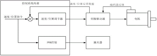
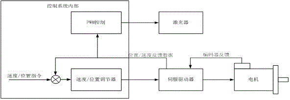
[0042] The cutting of multi-layer composite materials has strict and precise requirements on the energy output by the laser. It is necessary to cut through the upper material without damaging the lower material. In fact, the laser cutting control system is used to cut the object according to the pre-designed graphics , to form a laser energy cutting track to realize the cutting of the desired material layer.

[0043] In fact, each metal or non-metal material to be cut has a fixed laser energy that can cut through. The low-power laser on the laser cutting head can be controlled by PWM waves, which involves two control parameters: one is the pulse width. control, usin...


PUM


Abstract

The invention discloses a laser cutting machine and an energy control system of a laser cutting multilayer composite material. The energy control system is in data connection with a speed / position adjuster and a servo driver of a laser cutting head, and comprises a speed / position feedback data reading circuit, a DSP core circuit, a PWM output control circuit and a serial port communication module; the DSP core circuit is in double-direction data connection with the speed / position feedback data reading circuit, the PWM output control circuit and the serial port communication module; encoder signals fed back by the servo driver serve as speed fitting real-time data, and are fed back to the speed / position adjuster, speed data fed back by the laser cutting head in real time are read in real time, and the actual running speed of a current laser cutting head is fitted out; and due to the adoption of the speed vector fitting concept, real-time feedback of track speed is achieved, the control error is reduced, the laser output energy is precisely controlled, and cutting quality of pixel corners is improved.

Description

technical field [0001] The invention relates to the field of low-power laser cutting machines and their energy control systems, in particular to a precise energy output control system for laser cutting multilayer composite materials. Background technique [0002] At present, the processing technology of the commonly used low-power laser cutting machine for metal or non-metal cut materials is: first perforate to penetrate the cut material; Carry out a section of lead-in line cutting before the graphic element processing, and the lead-in line leads to the graphic element; then perform graphic element processing, and cut the graphics to be processed with a constant power; finally exit after the processing is completed. Obviously, this processing technology does not have high requirements for laser energy control, as long as it can cut through, it does not care about how to deal with excess laser energy. [0003] However, with the improvement of product processing requirements,...

Claims


Application Information

Patent Timeline
Patent Type & Authority Applications(China)
IPC IPC(8): B23K26/70B23K26/38B23K26/40
CPCB23K26/38B23K26/40B23K26/702
Inventor 张弢吴超何波祥
Owner 深圳市德堡数控技术有限公司
Why Eureka
Try Eureka