High Power Acoustic Vibration Generator

An acoustic vibration and generator technology, applied in the direction of fluid, electric components, fuel supply, etc. which utilize vibration, can solve the problems of increasing equipment weight, high equipment repair rate, complex equipment, etc., to reduce equipment leakage rate, assembly The effect of simple structure and light equipment

Active Publication Date: 2019-07-05
BEIJING DERONG HENGTONG ENVIRONMENTAL SCI & TECH
View PDF6 Cites 0 Cited by
  • Summary
  • Abstract
  • Description
  • Claims
  • Application Information

AI Technical Summary

Problems solved by technology

The internal structure of the acoustic wave dust remover is complicated, and the turntable adopts independent shafts and bearings. Correspondingly, the input disk and the output disk need to be processed with independent bearing seats to fix the bearings. The processing and assembly are time-consuming and laborious, and are prone to processing or assembly deviations.
This structure needs to use a coupling to connect the motor shaft and the shaft end of the sonic dust remover, which increases the complexity of the equipment and has high requirements for the concentricity of the motor shaft and the turntable shaft. For small factories with relatively imperfect fixtures, Its installation yield is low, and the equipment repair rate is high
This high-standard assembly process results in the gap between the turntable and the input and output disks not being less than 1 mm, otherwise it will seriously affect the yield of the equipment
At the same time, the equipment is complex and the weight of the equipment is increased. When installing on site, a support frame is required to support the bottom. In order to eliminate the influence caused by thermal expansion and contraction of the boiler, the structure of the support frame is complex and the cost is high.

Method used


Image

  • High Power Acoustic Vibration Generator
  • High Power Acoustic Vibration Generator

Examples


Embodiment Construction

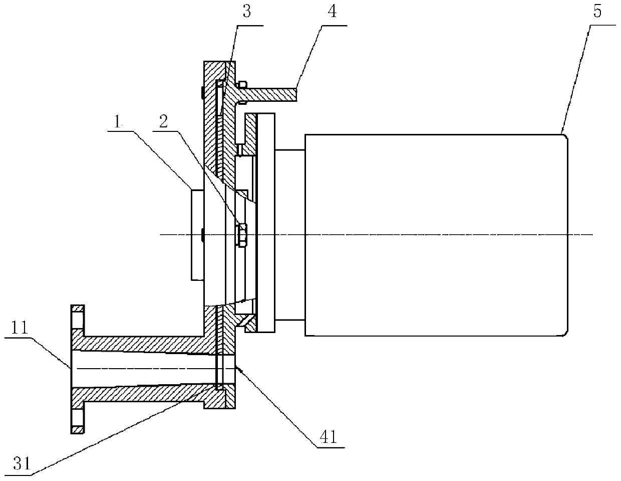
[0014] Such as figure 1 , The input disk 4, the sounding disk 3 and the output disk 1 are shown in cross-sectional view for clearly showing their structure. The high-power acoustic vibration generator of the present invention comprises input disk 4, sounding disk 3, output disk 1 and motor 5, and input disk 4 is provided with airflow input port 41, and output disk 1 is provided with sound output port 11, and input disk 4 and output The disks 1 are fastened together and fixed by bolts 2. The airflow input port 41 and the sound output port 11 are on the same center line. The sounding disk 3 is set between the input disk 4 and the output disk 1. There are gaps in between. The thickness of the sounding disc is 4.5-5.5 mm, and the gaps between the sounding disc, the input disc and the output disc are all less than 0.2 mm, and smooth air passages are formed inside the input disc 4 and the output disc 1 . The center of the sounding disk 3 is provided with a central hole, and the ou...


PUM


Abstract

The invention relates to the technical field of acoustic wave ash removing, and aims to provide a high-power acoustic vibration generator which is light in structure, simple to assemble and convenient in field installation. The high-power acoustic vibration generator comprises an input disc, a sound production disc, an output disc and a motor, and is characterized in that the input disc is provided with an air flow input port, the output disc is provided with a sound output port, the input disc and the output disc are buckled and fixed, the air flow input port and the sound output port are opposite to each other in a mode of sharing the same center line, the sound production disc is arranged between the input disc and the output disc, a clearance is reserved between the sound production disc and the input disc, a clearance is reserved between the sound production disc and the output disc, the periphery of the sound production disc is provided with a plurality of air flow cutting holes which are uniformly distributed in the circumferential direction, the motor is arranged at the outer side of the input disc and fixedly connected with the input disc, a motor shaft of the motor is directly connected with the sound production disc so as to drive the sound production disk to rotate, and the air flow cutting holes share the same center line with the air flow input port and the sound output port.

Description

technical field [0001] The invention relates to the technical field of acoustic wave ash removal, in particular to a high-power acoustic vibration generator. Background technique [0002] The sonic ash remover is a device that modulates compressed air into sound waves, which can be used for boiler ash removal. When in use, it will input sound waves into the boiler to remove ash from the heat exchange area of ​​the boiler. The internal structure of the current sonic dust remover is complicated, and the turntable adopts independent shafts and bearings. Correspondingly, the input disc and output disc need to be processed with independent bearing housings to fix the bearings. The processing and assembly are time-consuming and laborious, and are prone to processing or assembly deviations. This structure needs to use a coupling to connect the motor shaft and the shaft end of the sonic dust remover, which increases the complexity of the equipment and has high requirements for the c...

Claims


Application Information

Patent Timeline
Patent Type & Authority Patents(China)
IPC IPC(8): H02K7/08B06B1/20F23K1/00F23K3/00
CPCB06B1/20F23K1/00F23K3/00H02K7/08
Inventor 胡福生陈华锋
Owner BEIJING DERONG HENGTONG ENVIRONMENTAL SCI & TECH
Why Eureka
Try Eureka