Battery equalizer formed by multi-winding transformer

A multi-winding transformer and transformer technology, applied in charge equalization circuit, arrangement of multiple synchronous batteries, parallel conversion of batteries, etc., can solve the problems of reduced conversion efficiency, inability to reset the magnetic core, and failure of the magnetic reset circuit to achieve the cost. Low, simple circuit effect

Pending Publication Date: 2016-10-12
肖兴龙
View PDF10 Cites 2 Cited by
  • Summary
  • Abstract
  • Description
  • Claims
  • Application Information

AI Technical Summary

Problems solved by technology

[0003] The easiest way is to wind multiple windings on a magnetic core to make a voltage equalizer. Although many people have tried this, they have not achieved meaningful results. The reason is that the magnetic reset circuit has not given correct processing, so that There are two results obtained: 1. The magnetic core cannot be reset, so the actual machine cannot be made; 2. A special magnetic reset circuit must be added, which results in an increase in the size and cost of the circuit and a decrease in conversion efficiency.

Method used


Image

  • Battery equalizer formed by multi-winding transformer
  • Battery equalizer formed by multi-winding transformer
  • Battery equalizer formed by multi-winding transformer

Examples


Embodiment approach 1

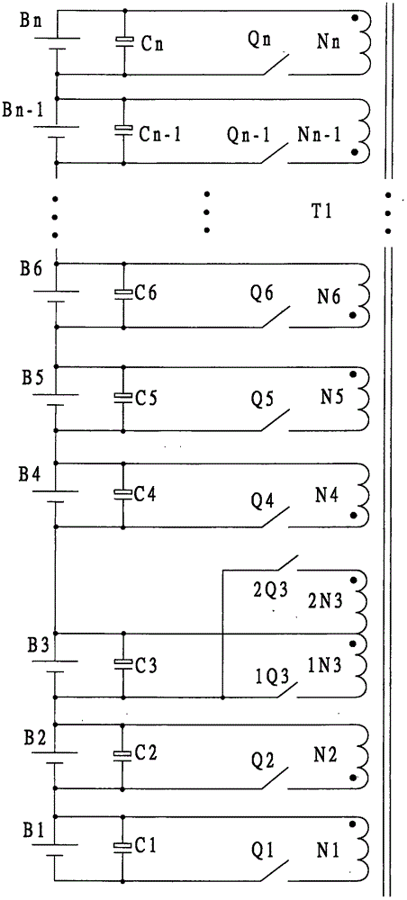
[0020] Embodiment 1, a single-transformer equalizer composed of a single-transistor forward circuit and a complementary push-pull circuit

[0021] Such as figure 1 As shown, the turns of each winding of the transformer T are all the same, that is, N1=N2=1N3=2N3=N4=N5=. . . =Nn, a single-transistor forward circuit is connected to the back of each battery, and a complementary push-pull circuit is connected to the back of the B3 battery; all switch tubes, Q1, Q2, 1Q3, 2Q3, Q4, Q5. . . Qn can be MOS tube, IGBT, etc.

[0022] It can be seen from the figure that the complementary push-pull circuit is composed of two single-tube forward circuits, and the corresponding winding directions of the two single-tube forward circuits are opposite.

[0023] According to the classification of the two winding directions of the transformer winding, all corresponding switching tubes are divided into two groups: group A switching tubes and group B switching tubes. Group A switching tubes ar...

Embodiment approach 2

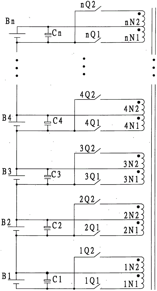
[0032] Embodiment 2, a single-transformer equalizer composed of complementary push-pull circuits

[0033] In order to further improve the balancing ability, the figure 1 The single-transistor forward circuits in the circuit are all changed into complementary push-pull circuits, and the equalization ability is doubled, such as figure 2 As shown, the number of turns of all windings in the figure is the same, that is, 1N1=-1N2=2N1=2N2=3N1==3N2=4N1=. . . =nN1=nN2; all switching tubes 1Q1, 1Q2, 2Q1, 2Q2, 3Q1, 3Q2. . . nQ1 and nQ2 can use MOS tubes, IGBTs, etc.

[0034] According to the classification of the two winding directions of the transformer winding, the switching tubes connected in series with the windings are divided into two groups: group A switching tubes and group B switching tubes. Group A switching tubes Q1, 2Q1, 3Q1, 4Q1. . . nQ1 is turned on and off at the same time; group B switching tubes Q2, 2Q2, 3Q2, 4Q2. . . nQ2 is turned on and off at the same ti...

Embodiment approach 3

[0041] Embodiment 3, multi-transformer equalizer composed of single-transistor forward and complementary push-pull circuits

[0042] For the case of a large number of batteries connected in series, the required number of coils cannot be wound on one magnetic core. In order to solve this problem, such as image 3 As shown, the equalizer uses multiple identical transformers, and the total number of transformers is m. Each transformer is added with a secondary winding Ns with the same number of turns on the basis of the transformer used in "Embodiment 1", and all transformers The secondary windings Ns of the transformer are all connected in parallel according to the principle of parallel connection of terminals with the same name; the composition characteristics of each transformer are: except for the added secondary coil Ns, the number of turns of all other windings is the same. All switching tubes can be MOS tubes, IGBTs, etc.

[0043] The working principle of the circuit is b...


PUM


Abstract

The invention discloses a battery equalizer formed by a multi-winding transformer, which is characterized in that multiple windings with the same turns and different winding directions are arranged on a magnetic core; each winding is serially connected with a switch transistor to form a single-transistor forward circuit or a complementary push-pull circuit to be parallelly connected onto the positive electrode and the negative electrode of each battery, which is as shown as in a figure 1. According to two wiring directions of the windings, switch transistors corresponding to the single-transistor forward circuits are divided into an A group of switch transistors and a B group of switch transistors, the A group of switch transistors and the B group of switch transistors are alternatively conducted and cut off when the circuit works, the interval time is the same, and the switch frequency adopts a high frequency. By using the working feature that the single-transistor forward circuits and the complementary push-pull circuits are combined together, natural magnetic reset of the magnetic core is realized, and voltage balancing of the whole battery pack can also be realized. in order to improve the balancing ability and adapt to balancing of a more number of battery packs, further measures are adopted: all single-transistor forward circuits are changed into the complementary push-pull circuit; and multiple transformers are used, secondary windings are added on the magnetic core of the transformer, and all secondary windings are all parallelly connected according to a principle that homonymous ends are parallelly connected.

Description

technical field [0001] This patent relates to the battery field, specifically a battery equalizer composed of a multi-winding transformer. Background technique [0002] For the battery pack to work normally and give full play to its efficacy, a battery equalizer must be used. Although lithium batteries have appeared for many years, the development of battery equalizers is very slow. Currently, there are very few equalizers that can be used on the market. . It is the common desire and goal of people to obtain a voltage equalizer with good cost performance. [0003] The easiest way is to wind multiple windings on a magnetic core to make a voltage equalizer. Although many people have tried this, they have not achieved meaningful results. The reason is that the magnetic reset circuit has not given correct processing, so that There are two results: 1. The magnetic core cannot be reset, so the actual machine cannot be made; 2. A special magnetic reset circuit must be added, whic...

Claims


Application Information

Patent Timeline
Patent Type & Authority Applications(China)
IPC IPC(8): H02J7/00
CPCH02J7/0019H02J7/0024H02P13/06
Inventor 肖兴龙
Owner 肖兴龙
Why Eureka
Try Eureka