Lithium ion battery charge and discharge protective circuit and lithium ion battery system

A technology for lithium-ion batteries and lithium-ion battery packs, applied in battery circuit devices, safety/protection battery circuits, circuit devices, etc., can solve the problem that a single MOS tube cannot meet the requirements of large current passage, unbalanced current distribution, and MOS tube Burned and other issues

Active Publication Date: 2016-10-12
深圳市德朗能电子科技有限公司
View PDF8 Cites 5 Cited by
  • Summary
  • Abstract
  • Description
  • Claims
  • Application Information

AI Technical Summary

Problems solved by technology

[0004] In recent years, lithium-ion batteries have been widely used in the fields of automobile starting batteries, electric vehicles and energy storage. Unlike the consumer field, the current of lithium-ion batteries in these application fields may be as high as 100 amperes or higher. At this time A single MOS tube cannot meet the requirements for passing large currents
like figure 1 As shown, for lithium-ion batteries with low current (such as tens of amperes of electric bicycles), it is usually solved by connecting multiple MOS tubes in parallel, but for protection circuits with hundreds of amperes or larger currents, multiple MOS tubes are usually used to solve the problem. The tubes M1~Mn are connected in parallel, which is not only bulky and expensive, but also easily burns out some MOS tubes due to unbalanced current distribution when there is a short circuit or a large current flows.

Method used


Image

  • Lithium ion battery charge and discharge protective circuit and lithium ion battery system
  • Lithium ion battery charge and discharge protective circuit and lithium ion battery system
  • Lithium ion battery charge and discharge protective circuit and lithium ion battery system

Examples


Embodiment 1

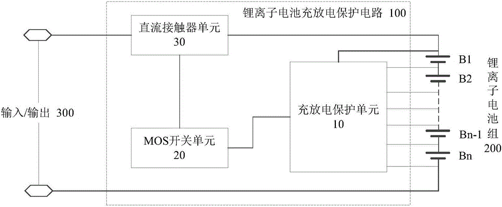
[0025] Such as figure 2 As shown, the lithium ion battery charge and discharge protection circuit of the present invention includes a charge and discharge protection unit 10 connected to the lithium ion battery pack 200, and a DC contactor unit 30 connected to the input / output 300 and the charge and discharge circuit of the lithium ion battery pack 200 , and a MOS switch unit 20 connected to both the charge and discharge protection unit 10 and the DC contactor unit 30 . Wherein, the charge and discharge protection unit 10 performs real-time data collection, judgment and comparison on the lithium-ion battery pack 200 and outputs a control signal; the MOS switch unit 20 controls the DC contactor unit 30 to disconnect or conduct the lithium-ion battery pack 200 according to the control signal. The charging and discharging circuit.

[0026] The charge and discharge protection unit of the lithium ion battery charge and discharge protection circuit of the present invention perform...

Embodiment 2

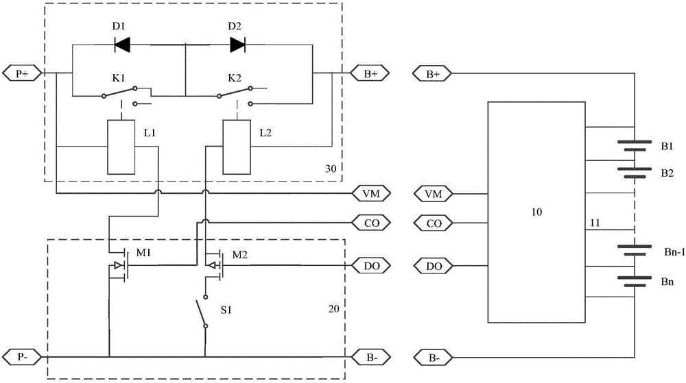
[0032] Such as image 3 As shown, in the lithium ion battery charge and discharge protection circuit of this embodiment, the lithium ion battery protection chip of the charge and discharge protection unit 10 is a lithium ion battery protection chip with a common negative electrode structure, and the DC contactor unit 30 also includes a DC contactor K1 Diode D1 connected in parallel, at this time, the MOS switch M1 of the MOS switch unit 20 is an NMOS tube, and the MOS switch M2 is a PMOS tube; the corresponding lithium ion battery charge and discharge protection circuit is specifically: the charge and discharge protection unit 10 is connected to the lithium ion battery Between the positive terminal B+ and the negative terminal B- (that is, the two-polarity terminal) of the group 200, the DC contactor unit 30 is connected between the input / output positive terminal P+ and the positive terminal B+ (that is, the same polarity terminal), and the MOS switch unit 20 is connected to t...

Embodiment 3

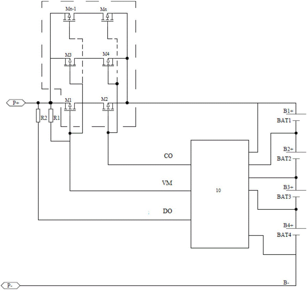
[0040] Such as Figure 4 As shown, in the lithium ion battery charge and discharge protection circuit of this embodiment, the lithium ion battery protection chip of the charge and discharge protection unit 10 is a lithium ion battery protection chip with a common anode structure, and the DC contactor unit 30 also includes a DC contactor K1 Diode D1 connected in parallel, at this time, the MOS switch M1 of the MOS switch unit 20 is a PMOS tube, and the MOS switch M2 is an NMOS tube; the corresponding lithium ion battery charge and discharge protection circuit is specifically: the charge and discharge protection unit 10 is connected to the lithium ion battery Between the positive terminal B+ and the negative terminal B- of the battery pack 200, the MOS switch unit 20 and the DC contactor unit 30 are connected in series between the negative terminal P- of the input / output 300 and the negative terminal B- of the lithium-ion battery pack 200 , the MOS switch unit 20 is connected to...


PUM


Abstract

The invention discloses a lithium ion battery charge and discharge protective circuit. The lithium ion battery charge and discharge protective circuit comprises an MOS (Metal Oxide Semiconductor) switch unit, a charge and discharge protective unit and a direct current contactor unit, wherein the charge and discharge protective unit and the direct current contactor unit are connected with the MOS switch unit; the charge and discharge protective unit carries out data real-time acquisition and data judgment and comparison on a lithium ion battery pack and outputs a control signal; when an abnormal situation such as over-charge or over-discharge and the like occurs in the lithium ion battery pack, the charge and discharge protective unit outputs the control signal of a charge abnormity or a discharge abnormity; the MOS switch unit controls the direct current contactor unit to switch off or switch on a charge and discharge circuit according to the control signal so as to achieve the effect of protecting the lithium ion battery pack. Meanwhile as a direct current contactor can enable high working currents to pass, the circuit is suitable for a lithium ion battery system for charge and discharge of high current more than hectoampere.

Description

technical field [0001] The invention relates to the technical field of battery charge and discharge protection, in particular to a lithium ion battery charge and discharge protection circuit and a lithium ion battery system. Background technique [0002] Lithium-ion battery is a secondary battery (rechargeable battery) that mainly relies on the movement of lithium ions between the positive and negative electrodes to work. During charging and discharging, Li+ intercalates and deintercalates back and forth between the two polar terminals. During charging, Li+ deintercalates from the positive electrode, intercalates into the negative electrode through the electrolyte, and the negative electrode is in a lithium-rich state; the opposite is true during discharge. Lithium-ion battery is an electric energy storage device widely used in the field of consumer electronics and power storage. There are protection circuits in actual use, and the protection circuits usually have functions...

Claims


Application Information

Patent Timeline
Patent Type & Authority Applications(China)
IPC IPC(8): H02J7/00
CPCH02J7/0026
Inventor 杨洪雁吴江伟
Owner 深圳市德朗能电子科技有限公司
Why Eureka
Try Eureka