Multi-transformer combined ultrahigh voltage generation device

An ultra-high voltage, generating device technology, applied in transformers, transformers/inductor coils/windings/connections, circuits, etc., to achieve the effects of reducing reflection stress, high efficiency, and increasing output voltage

Active Publication Date: 2016-10-12
浙江赫茨电气有限公司
View PDF5 Cites 2 Cited by
  • Summary
  • Abstract
  • Description
  • Claims
  • Application Information

AI Technical Summary

Problems solved by technology

[0005] The purpose of the present invention is to overcome the shortcomings that the existing high-voltage power supply cannot meet the requirements of long-distance arc ignition, and provide a multi-transformer combination ultra-high voltage generator that outputs a sufficiently high arc ignition voltage to meet the requirements of long-distance arc ignition for plasma devices. Arc requirements, higher energy and higher efficiency in the disposal of industrial hazardous substances, medical waste, and domestic waste

Method used


Image

  • Multi-transformer combined ultrahigh voltage generation device
  • Multi-transformer combined ultrahigh voltage generation device
  • Multi-transformer combined ultrahigh voltage generation device

Examples


Embodiment 1

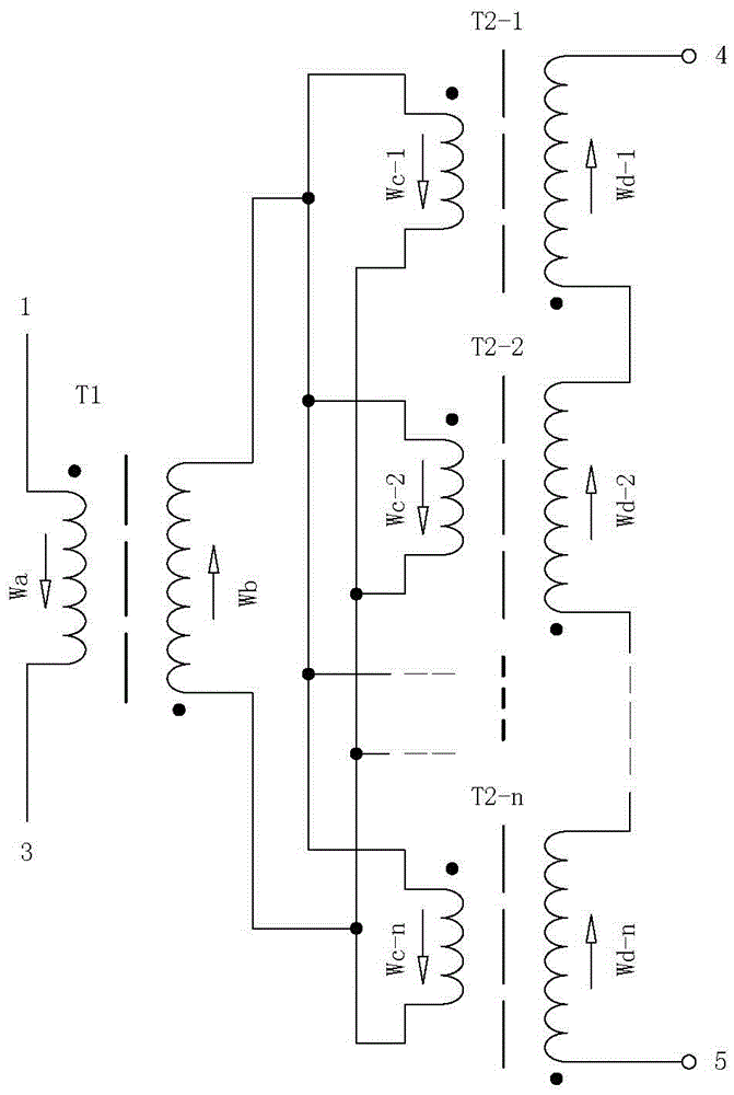
[0019] Example 1 figure 1 In the illustrated embodiment, the multi-transformer combination ultra-high voltage generator consists of an intermediate transformer unit (T1) and multiple high-voltage transformer units, wherein the intermediate transformer unit (T1) includes a primary side coil (Wa) and a secondary side coil (Wa) The coil (Wb), the primary side coil (Wa) and the secondary side coil (Wb) are nested, and the primary side coil (Wa) is set in the inner layer; the high voltage transformer unit includes the primary coil and the secondary high voltage coil, the primary coil and The secondary high-voltage coils are nested, the secondary high-voltage coils are set on the outer layer, and the secondary high-voltage coils are wound on the skeleton in a lattice winding manner; the primary coils of multiple high-voltage transformer units are connected in parallel with the end of the same name Afterwards, the primary-side electrical circuit is formed, and the secondary high-v...

Embodiment 2

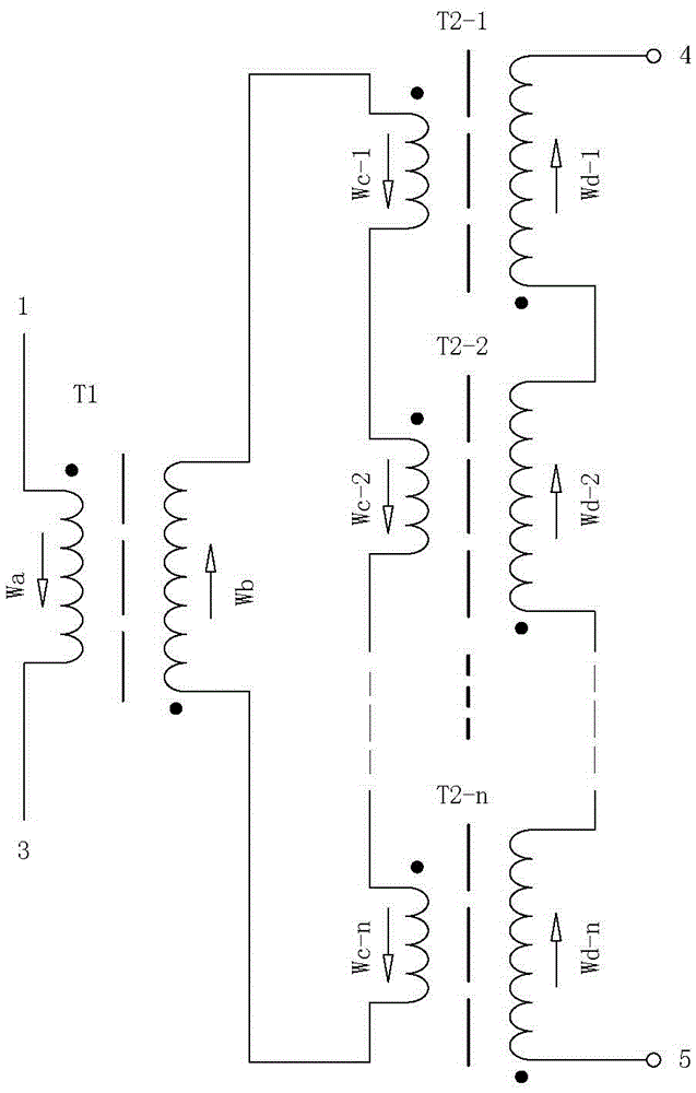
[0020] Example 2 figure 2 In the illustrated embodiment, the multi-transformer combination ultra-high voltage generator consists of an intermediate transformer unit (T1) and multiple high-voltage transformer units, wherein the intermediate transformer unit (T1) includes a primary side coil (Wa) and a secondary side coil (Wa) The coil (Wb), the primary side coil (Wa) and the secondary side coil (Wb) are nested, and the primary side coil (Wa) is set in the inner layer; the high voltage transformer unit includes the primary coil and the secondary high voltage coil, the primary coil and The secondary high-voltage coils are nested, the secondary high-voltage coils are arranged on the outer layer, and the secondary high-voltage coils are wound on the skeleton in a lattice winding manner; the primary coils of each high-voltage transformer unit are connected in series in the forward direction. The primary side electrical circuit is formed, and the secondary high voltage coils of e...

Embodiment 3

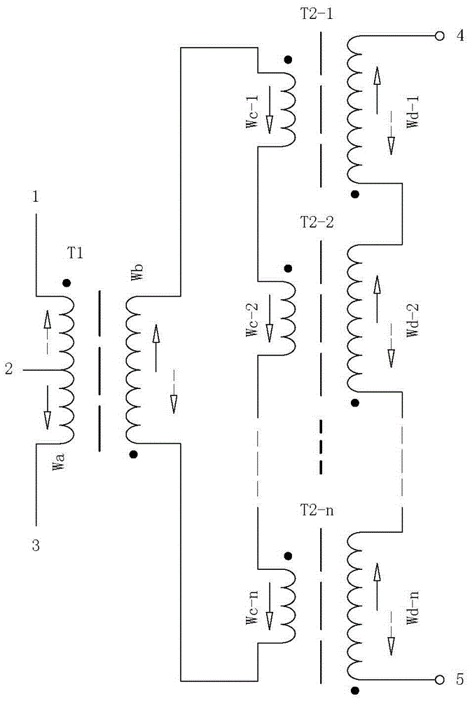
[0021] Example 3 image 3In the embodiment shown, the multi-transformer combined ultra-high voltage generating device is based on the second embodiment, the primary side coil (Wa) in the intermediate transformer unit (T1) has a center tap (2), and the center Tap (2) is used to connect the input power. Other structures are the same as those of the second implementation, and will not be repeated here.


PUM


Abstract

The invention provides a multi-transformer combined ultrahigh voltage generation device and relates to a high-voltage power supply device. The multi-transformer combined ultrahigh voltage generation device is composed of a relay transformer unit and a plurality of high-voltage transformer units, wherein the relay transformer unit comprises a primary side coil and a secondary side coil, and the primary side coil is arranged on an inner layer; each high-voltage transformer unit comprises a primary coil and a secondary high-voltage coil, and the secondary high-voltage coil is arranged on an outer layer; the primary coils of all the high-voltage transformer units are connected with one another to form a primary side electric circuit; the secondary high-voltage coils of all the high-voltage transformer units are overlapped with one another forwardly to be output; the secondary side coil of the relay transformer unit is connected with the plurality of high-voltage transformer units to form a primary side electric circuit. With the adoption of the multi-transformer combined ultrahigh voltage generation device, high voltage generated by the secondary high-voltage coils of the plurality of high-voltage transformers are overlapped to ultrahigh voltage to be output, so that the requirement on long-distance arc strike of a plasma device is met.

Description

technical field [0001] The invention relates to electronic circuits, in particular to a high-voltage power supply device. Background technique [0002] At present, plasma technology has been widely used. The way of using plasma to dispose of industrial hazardous substances, medical waste, and domestic waste is quite different from the general incineration method. Plasma is a state formed under the ionosphere or discharge phenomenon. , the discharge effect makes the working gas molecules lose the outer electrons and form an ion state, which generates high temperature through mutual collision. Recombine to generate new substances, so that harmful substances become harmless substances. High-voltage arc ignition power supply is required in the disposal of industrial hazardous substances, medical waste, and domestic waste plasma equipment. [0003] Using a plasma spray gun to heat and decompose water vapor as a gasification agent to gasify coal or garbage will become the first ...

Claims


Application Information

Patent Timeline
Patent Type & Authority Applications(China)
IPC IPC(8): H01F38/16H01F27/28H01F27/29
CPCH01F38/16H01F27/28H01F27/29
Inventor 周开根
Owner 浙江赫茨电气有限公司
Why Eureka
Try Eureka