Multi-transformer series connection type power output circuit

A power output and transformer technology, applied in the field of power output circuits, to achieve the effects of avoiding damage, high efficiency, and high energy

Inactive Publication Date: 2016-11-23
QUZHOU YUNRUI IND DESIGN
View PDF4 Cites 2 Cited by
  • Summary
  • Abstract
  • Description
  • Claims
  • Application Information

AI Technical Summary

Problems solved by technology

[0005] The purpose of the present invention is to overcome the disadvantage that the existing high-voltage power supply cannot meet the requirements of long-distance arc ignition, and provide a power output circuit with multiple transformers in series, which can output a sufficiently high arc ignition voltage to meet the long-distance arc ignition requirements of the plasma device. Higher energy and higher efficiency in the disposal of industrial hazardous substances, medical waste, and domestic waste

Method used


Image

  • Multi-transformer series connection type power output circuit
  • Multi-transformer series connection type power output circuit

Examples


Embodiment 1

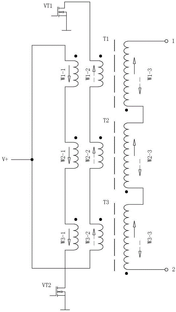
[0015] Example 1 figure 1 In the embodiment shown, the power output circuit with multiple transformers connected in series is composed of a first power switch tube (VT1), a second power switch tube (VT2) and multiple high-voltage transformer units, wherein the high-voltage transformer unit consists of a primary coil and a secondary coil. The primary high-voltage coil consists of a first primary coil and a second primary coil, the first primary coil and the second primary coil are wound in parallel with two wires, and the secondary high-voltage coil is wound on the On the frame, the primary coil and the secondary high-voltage coil are nested, the first primary coil and the second primary coil are set on the inner layer, and the secondary high-voltage coil is set on the outer layer; there are more than two high-voltage transformer units, and multiple high-voltage transformer units The first primary coils of multiple high-voltage transformer units are connected in series in forwa...

Embodiment 2

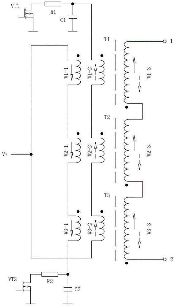
[0016] Example 2 figure 2 In the shown embodiment, on the basis of the first embodiment, there is a second absorbing capacitor (C2) between the tail end of the first primary low-voltage circuit and the ground wire, and between the head end of the second primary low-voltage circuit and the ground wire. There is a first absorption capacitor (C1) between the ground wires. The first absorption capacitor (C1) and the second absorption capacitor (C2) are used to absorb the reverse peak voltage generated by each high-voltage transformer to avoid damage to the power switching device; in the first primary There is a second current limiting resistor (R2) between the end of the low-voltage loop and the drain of the second power switch (VT2), and between the head of the second primary low-voltage loop and the drain of the first power switch (VT1). There is a first current-limiting resistor (R1) between the poles, the first current-limiting resistor (R1) and the second current-limiting re...


PUM


Abstract

The invention discloses a multi-transformer series connection type power output circuit and relates to a high-voltage source power output circuit. The multi-transformer series connection type power output circuit is composed of a first power switch tube, a second power switch tube and multiple high-tension transformer units, wherein first primary coils of the high-tension transformer units are connected in series in a straight-forward mode to form a first primary low-tension loop, secondary primary coils of the high-tension transformer units are connected in series in a straight-forward mode to form a second primary low-tension loop, and secondary high-tension coils of the high-tension transformer units conduct straight-forward superposition output; an input power supply is connected to the head end of the first primary low-tension loop and the tail end of the second primary low-tension loop, the tail end of the first primary low-tension loop is connected with a drain electrode of the second power switch tube, and the head end of the second primary low-tension loop is connected to a drain electrode of the first power switch tube. By the adoption of the multi-transformer series connection type power output circuit, superposition output of high-tension electricity generated on all the secondary high-tension coils is achieved, output voltage is increased greatly, and the requirement for long-distance arc striking of a plasma device is met.

Description

technical field [0001] The invention relates to electronic circuits, in particular to a power output circuit of a high-voltage power supply. Background technique [0002] At present, plasma technology has been widely used. The way of using plasma to dispose of industrial hazardous substances, medical waste, and domestic waste is quite different from the general incineration method. Plasma is a state formed under the ionosphere or discharge phenomenon. , the discharge effect makes the working gas molecules lose the outer electrons and form an ion state, which generates high temperature through mutual collision. Recombine to generate new substances, so that harmful substances become harmless substances. High-voltage arc ignition power supply is required in the disposal of industrial hazardous substances, medical waste, and domestic waste plasma equipment. [0003] Using a plasma spray gun to heat and decompose water vapor as a gasification agent to gasify coal or garbage wil...

Claims


Application Information

Patent Timeline
Patent Type & Authority Applications(China)
IPC IPC(8): H02M7/49
CPCH02M7/49H02M1/0077
Inventor 周开根
Owner QUZHOU YUNRUI IND DESIGN
Why Eureka
Try Eureka