Central hot water recycling system

A hot water circulation and central technology, applied in the field of solar thermal energy utilization, can solve problems such as waste of resources, limited roof area, user troubles, etc., to achieve the effect of ensuring freedom and full utilization

Inactive Publication Date: 2016-10-12
安徽省恒胜机电工程股份有限公司
View PDF6 Cites 1 Cited by
  • Summary
  • Abstract
  • Description
  • Claims
  • Application Information

AI Technical Summary

Problems solved by technology

However, since most of the cities are dominated by high-rise buildings now, due to the large number of users of high-rise buildings and the limited roof area, most high-rise building users use instant gas water heaters and plug-in water heaters, which causes waste of resources and increases cost of living
Some high-rise buildings have a unified central hot water supply unit. This kind of central hot water supply unit is equipped with a hot water flow statistics module, and the fee is charged according to the amount of consumption of the residents; Water is divided into households, which will cause some users to use hot water when they need to use hot water, which will cause inconvenience to users.
And this kind of central hot water supply unit can only be used when the water temperature reaches the preset value, ignoring the problem that different users have different requirements for water temperature, and also causing troubles to users
Furthermore, during the time when the solar radiation heat is relatively high, after the water temperature in the container for storing hot water is close to 100°C, the temperature does not rise any more. At this time, the heat radiated by the sun cannot be continuously utilized, resulting in the disadvantage of energy waste

Method used


Image

  • Central hot water recycling system

Examples


Embodiment Construction

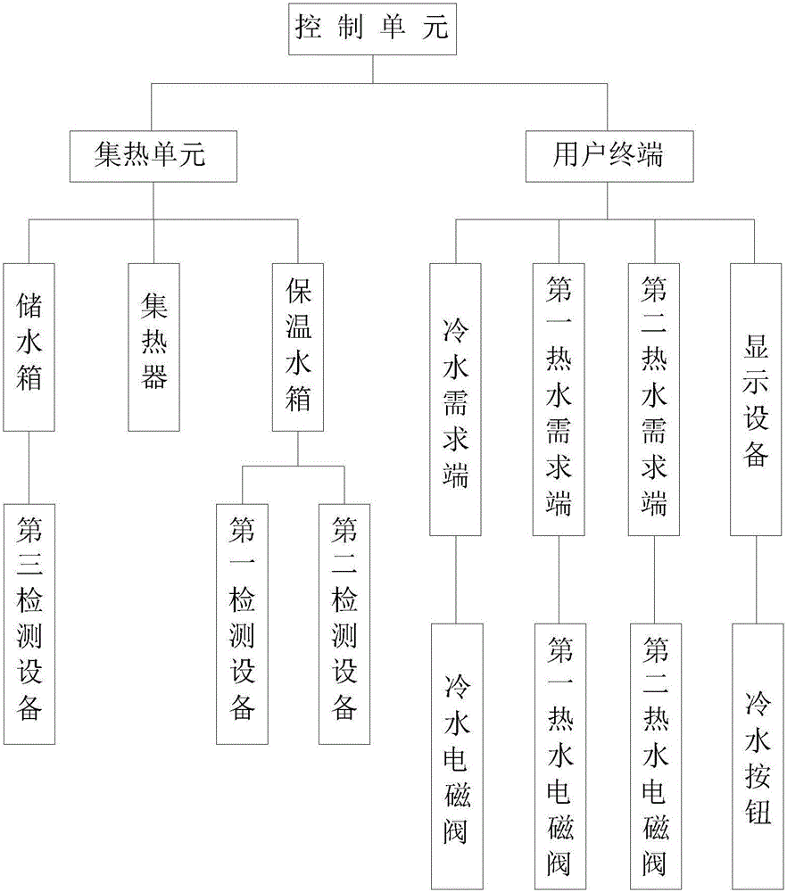
[0022] Such as figure 1 as shown, figure 1 It is a central hot water recycling system proposed by the present invention.

[0023] refer to figure 1 , the central hot water recycling system proposed by the present invention includes: a plurality of heat collecting units, a plurality of user terminals, and a control unit; the heat collecting units correspond to the user terminals one by one;

[0024] Any heat collecting unit among the plurality of heat collecting units includes a heat collector, a thermal insulation water tank and a water storage tank; the heat collector is connected with the pipeline of the thermal insulation water tank; There is a water valve; the heat collector is used to collect the heat energy of solar radiation, and use the above heat energy to heat the water in the heat preservation water tank; the heat preservation water tank is provided with a water inlet and a water outlet, and the water inlet is connected with a water inlet pipe and the water outlet...


PUM


Abstract

The invention discloses a central hot water recycling system, comprising: a plurality of heat collecting units, a plurality of user terminals, and a control unit; the control unit acquires the detection value of the second detection device in any one of the heat collecting units, and The above detection value is compared with the preset value stored in the control unit, and according to the comparison result, the cold water solenoid valve and the first hot water solenoid valve in the user terminal corresponding to the heat collection unit are controlled to operate; The detection value of the first detection device in a heat collection unit, and compare the above detection value with the highest temperature value, and control the water valve action according to the comparison result; the control unit obtains the first detection device in any heat collection unit The detection value of the second detection device and the detection value of the third detection device, and the above three detection values ​​are sent to the display device in the user terminal corresponding to the heat collection unit for display.

Description

technical field [0001] The invention relates to the technical field of solar thermal energy utilization, in particular to a central hot water recycling system. Background technique [0002] Solar energy is a clean natural renewable energy, inexhaustible and inexhaustible, and it is an energy that everyone can share. At present, mankind has made remarkable progress in the utilization of solar energy, especially in the field of solar water heaters, which are widely used. However, since most of the cities are dominated by high-rise buildings now, due to the large number of users of high-rise buildings and the limited roof area, most high-rise building users use instant gas water heaters and plug-in water heaters, which causes waste of resources and increases cost of living. Some high-rise buildings have a unified central hot water supply unit. This kind of central hot water supply unit is equipped with a hot water flow statistics module, and the fee is charged according to th...

Claims


Application Information

Patent Timeline
IPC IPC(8): F24D17/00F24D19/10
CPCF24D17/0021F24D19/1057F24D2200/14
Inventor 梅升月
Owner 安徽省恒胜机电工程股份有限公司
Why Eureka
Try Eureka