Decompression structure applied to conveyance of natural gas pipeline

A natural gas pipeline and pressure relief structure technology, applied to pipe components, pipes/pipe joints/fittings, mechanical equipment, etc., can solve problems such as fire, shutdown, high pressure relief valve leakage, etc., to reduce the possibility of shaking , Guarantee the service life and the effect of uniform force

Inactive Publication Date: 2016-10-12
CHENGDU GUOGUANG ELECTRONICS INSTR
View PDF4 Cites 2 Cited by
  • Summary
  • Abstract
  • Description
  • Claims
  • Application Information

AI Technical Summary

Problems solved by technology

However, when there is overpressure in the long-distance pipeline in the prior art, the high-pressure relief valve often fails to open and release pressure normally, which brings great harm to the transportation of the oil pipeline. Cause fire, etc.; on the other hand, there are also defects that the high-pressure relief valve leaks, or cannot be closed normally after opening

Method used


Image

  • Decompression structure applied to conveyance of natural gas pipeline

Examples


Embodiment 1

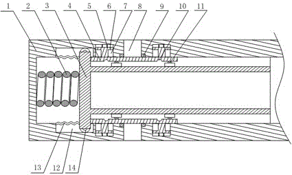
[0020] Such as figure 1 As shown, this embodiment includes a tubular casing 1 with one end closed and a piston 3 placed inside the casing 1. The piston 3 is a cylinder with one end closed, and the outer peripheral wall of the closed end of the piston 3 expands outwards to It is in contact with the inner wall of the housing 1, and an annular space is formed between the main part of the piston 3 and the inner wall of the housing 1, and a first spring 2 is provided between the inner wall of the closed end of the housing 1 and the end surface of the closed end of the piston 3 , at least one pressure relief hole 8 communicating with the annular space is opened on the shell 1, and two blind holes 7 are opened on the inner wall of the shell 1, and the two blind holes 7 are symmetrically arranged in the pressure relief hole 8, on both sides, the blind hole 7 is provided with a second spring 5, one end of the T-shaped movable block 6 is connected with the second spring 5 and is slidabl...


PUM


Abstract

The invention discloses a decompression structure applied to conveyance of a natural gas pipeline. The decompression structure comprises a shell and a piston, wherein the piston is a cylinder with one closed end, and the external circumferential wall of the closed end of the piston expands outwards to be in contact with the inner wall of the shell; a first spring is arranged between the inner wall of the shell and the closed end of the piston; a decompression hole is formed in the shell; two blind holes are formed in the inner wall of the shell, a second spring is arranged in each blind hole, one end of a corresponding movable block is connected with the corresponding second spring, and the other end of the movable block is connected with a corresponding sealing plate; grooves are formed in the inner side walls of the sealing plates, and balls matched with the grooves are arranged on protrusions. According to the decompression structure applied to the conveyance of the natural gas pipeline, reciprocating movement of the piston is achieved by deformation and deformation recovery of the first spring and the second spring, so that sealing and opening of the sealing plates to the decompression hole are achieved; torsion springs are selected to meet non-directional applied stress generated due to the fact that the first spring and the second spring continuously impact the piston in order to adapt to air with unstable flow rate, thereby ensuring service lives of the first spring and the second spring.

Description

technical field [0001] The invention relates to a pipeline pressure relief device, in particular to a pressure relief structure for natural gas pipeline transportation. Background technique [0002] Long-distance pipelines refer to long-distance pipelines used to transport commodity media, such as oil and gas, across provinces, cities, across rivers, roads, etc. . The long-distance gas pipeline is the main artery of the national economy, directly serving the production of industries along the line and the ordinary life of urban residents. However, the pipeline is also a source of danger. For high-pressure gas pipelines, the internal pressure is relatively high, and all combustible gases are transported. During the transportation process, if the air pressure is unstable, it may cause the pressure in the pipeline to be too high and cause an explosion. . If natural gas is transported in the pipeline, once an explosion occurs, it will cause a fire, and the flammable and explo...

Claims


Application Information

Patent Timeline
Patent Type & Authority Applications(China)
IPC IPC(8): F16L55/07
CPCF16L55/07
Inventor 吕忠贵
Owner CHENGDU GUOGUANG ELECTRONICS INSTR
Why Eureka
Try Eureka