Novel vertical multistage pump

A multi-stage pump, vertical technology, applied in the direction of non-variable pumps, non-volume pumps, pumps, etc., can solve the problems of unfavorable pump normal operation, large load pressure, high working pressure, etc., to improve the reliability of use Improvement of performance and service life, improvement of pump efficiency, and reduction of axial force

Active Publication Date: 2016-10-12
无锡艾比德泵业有限公司
View PDF5 Cites 13 Cited by
  • Summary
  • Abstract
  • Description
  • Claims
  • Application Information

AI Technical Summary

Problems solved by technology

[0002] The vertical multistage pump is a kind of power equipment that greatly improves the energy of the liquid, and its working pressure is relatively high. The structure of the vertical multistage pump in the prior art is: a casing, and a pump shaft is installed in the casing. An impeller is installed on the pump shaft, and a balance drum or a balance disc is installed on the pump shaft at the top of the impeller, and the top of the balance drum or balance disc is sealed by a shaft seal; the inlet pressure of each impeller is lower than the outlet pressure, and the balance drum position, the pressure of the lower part is greater than the pressure of the upper part, and the balance drum or balance plate balances the axial force of the part. Since the balance drum or balance plate releases pressure through the gap, the balance chamber communicates with the low-pressure chamber of the water inlet chamber, and the leakage is serious. For small flow and high The effect of the efficiency reduction of head multi-stage pumps is particularly obvious
[0003] For vertical multistage pumps with small flow rate and high head, the pressure behind the last stage impeller is very high. If measures to balance the axial force are not taken, it will cause a lot of load pressure on the bearings, which is not conducive to the normal operation of the pump. The traditional design generally adopts the above-mentioned The balance drum or balance disc structure can balance part of the axial force, but the leakage is large, which reduces the pump efficiency a lot

Method used


Image

  • Novel vertical multistage pump
  • Novel vertical multistage pump

Examples


Embodiment Construction

[0019] The specific implementation manner of the present invention will be described below in conjunction with the accompanying drawings.

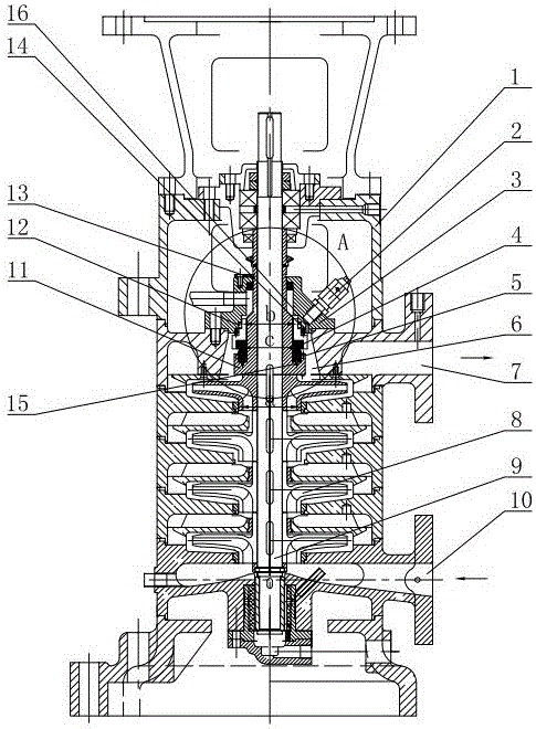
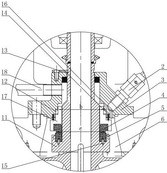
[0020] Such as figure 1 and figure 2 As shown, the novel vertical multistage pump of this embodiment includes a pump housing 1, a pump shaft 9 is installed in the pump housing 1, a plurality of impellers 8 are installed on the pump shaft 9, and the inlet pressure of each impeller 8 is Less than the outlet pressure, a semi-packaged mechanical seal is installed on the pump shaft 9 at the top of the impeller 8. The structure of the semi-packaged mechanical seal is: including a mechanical seal shaft sleeve 11, which is provided with a card slot. The inside of the card slot is inlaid with the moving ring 5 through the anti-rotation pin 15; the mechanical seal shaft sleeve 11 is covered with a static ring seat 17 on the outer circumferential surface above the moving ring 5, and the bottom of the static ring seat 17 has a groove, and the groove...


PUM


Abstract

The invention discloses a novel vertical multistage pump. The novel vertical multistage pump comprises a pump body shell; a pump shaft is mounted in the pump body shell, and is provided with multiple impellers; a half-integrated mechanical seal is mounted on the pump shaft at the tops of the impellers, and includes a machine seal shaft sleeve; the machine seal shaft sleeve is provided with a clamping groove; a movable ring is embedded in the clamping groove; the machine seal shaft sleeve is coated with a static ring base on the outer peripheral surface on the movable ring, and is provided with a groove in the bottom; a static ring is tightly matched and embedded in the groove, and is tightly bonded with a friction surface of the movable ring; two steps are arranged on the outer peripheral surface of the static ring base, and are respectively a large step and a small step; the large step is connected with a machine seal gland through multiple small springs; meanwhile, the small step is sealed with the machine seal gland through a sealing ring; a high-pressure cavity is betwen the outer side of the half-integrated mechanical seal and the inner wall surface of the pump body shell; an input port is in the lower part of one end of the pump body shell; and an output port is in the upper part of one end of the pump body shell, and is communicated with an outlet of the final-stage impeller. The novel vertical multistage pump is excellent in reliability and long in service life.

Description

technical field [0001] The invention relates to the technical field of water pumps, in particular to a novel vertical multistage pump. Background technique [0002] The vertical multistage pump is a kind of power equipment that greatly improves the energy of the liquid, and its working pressure is relatively high. The structure of the vertical multistage pump in the prior art is: a casing, and a pump shaft is installed in the casing. An impeller is installed on the pump shaft, and a balance drum or a balance disc is installed on the pump shaft at the top of the impeller, and the top of the balance drum or balance disc is sealed by a shaft seal; the inlet pressure of each impeller is lower than the outlet pressure, and the balance drum position, the pressure of the lower part is greater than the pressure of the upper part, and the balance drum or balance plate balances the axial force of the part. Since the balance drum or balance plate releases pressure through the gap, the ...

Claims


Application Information

Patent Timeline
Patent Type & Authority Applications(China)
IPC IPC(8): F04D1/06F04D29/12F04D29/22
CPCF04D1/06F04D29/126F04D29/2266
Inventor 王金凤杨超君杜志高
Owner 无锡艾比德泵业有限公司
Why Eureka
Try Eureka