Wheel-direction flow force extension roller blind water wheel or wind wheel and power generation system

A rolling shutter and flow force technology, applied in the field of wheel flow force impellers, can solve problems such as unsatisfactory, insufficient utilization of hydraulic and wind resources, etc., and achieve the effect of low maintenance cost and strong resistance to damage

Inactive Publication Date: 2016-10-12
毛永波
View PDF7 Cites 1 Cited by
  • Summary
  • Abstract
  • Description
  • Claims
  • Application Information

AI Technical Summary

Problems solved by technology

[0002] The current hydropower wind power generation equipment is quite mature, but the development of tide, river bed power generation, universal ocean current hydropower, and universal wind power generation equipment is not satisfactory, and the hydropower and wind power resources have not been fully utilized.

Method used


Image

  • Wheel-direction flow force extension roller blind water wheel or wind wheel and power generation system
  • Wheel-direction flow force extension roller blind water wheel or wind wheel and power generation system
  • Wheel-direction flow force extension roller blind water wheel or wind wheel and power generation system

Examples


Embodiment Construction

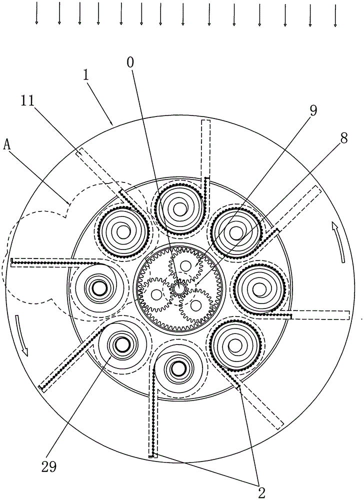
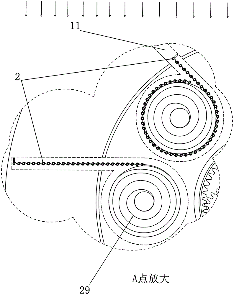
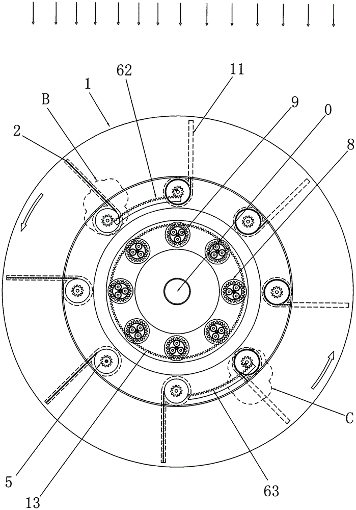
[0035] A kind of wheel direction flow telescopic roller shutter water wheel or wind wheel, such as figure 1 , 2 As shown, it includes: a runner 1, a central shaft 0, a roller blind 2, a reel 20 and a telescopic device 29; the central shaft 0 is the rotation center axis of the runner 1; the runner 1 is coaxially socketed The central axis 0; the reel 20 rotates at a fixed point and is distributed in multiple circles on the runner 1, and its axis is parallel to the central axis 0 of the runner 1 or its axis is perpendicular to the central axis of the runner 1 0; the roller blind 2 is a plurality of hard metal strips or plastic strips that are hinged to each other, and the sheet curtain or venetian blind is connected to the reel by the edge or corner of the sheet curtain or venetian blind. 20 and be stretched into the water-resisting and wind-resisting curtain film and complex sliding telescopic on the slide track 11 of runner 1, its end is provided with corner plate or anti-buck...


PUM


Abstract

The invention discloses a wheel-direction flow force extension roller blind water wheel or wind wheel and a wheel-direction flow force extension roller blind water wheel or wind wheel power generation system. The wheel-direction flow force extension roller blind water wheel or wind wheel power generation system comprises a rotating wheel, a central shaft, roller blinds, reels, elastic devices and one or more power generation sets. The roller blinds are slidingly arranged on the rotating wheel; the extension devices are directly connected with the roller blinds or are connected with the reels to drive the roller blinds to be elastic on the rotating wheel; under the action of water power and wind power, the roller blinds at one side of the rotating wheel protrude by the effect of a flow force and is in a water retaining stressed state, the roller blinds at the other side of the rotating wheel automatically roll under the action of the elastic devices, and a water flow generates no thrust on the roller blinds. In this way, the two sides of the rotating wheel are stressed in an unbalanced manner, thus the rotating wheel rotationally drives the one or more power generation sets. Submerged slow flow power generation scheme and large scale equipment are provided for tides, riverbeds, water pipe air ducts, universal ocean current water power and universal wind power; and the wheel-direction flow force extension roller blind water wheel or wind wheel and the power generation system have the characteristics of high motive power, high resistance to damage, and low maintenance cost.

Description

【Technical field】 [0001] The invention relates to hydraulic wind power equipment, in particular to the field of wheeled flow impellers. 【Background technique】 [0002] The current hydro-wind power generation equipment has developed quite maturely, but the development of sea tide, river bed power generation, universal ocean current hydropower, and universal wind power generation equipment is not satisfactory, and the hydro-wind power resources have not been fully utilized. 【Content of invention】 [0003] The purpose of the present invention is to provide a submersible slow-current power generation scheme and large-scale equipment for sea tides, river beds, water pipe air ducts, universal ocean current hydraulic power and universal wind power. [0004] The present invention adopts following technical scheme: [0005] A wheel-to-flow stretchable roller blind water wheel or wind wheel, which includes: a runner, a central shaft, a roller blind, a reel, and a telescopic device;...

Claims


Application Information

Patent Timeline
Patent Type & Authority Applications(China)
IPC IPC(8): F03B13/00F03B13/10F03B3/14F03B3/12F03D9/25F03D3/06
CPCF03B3/123F03B3/14F03B13/00F03B13/10F03D3/061F03D3/062F05B2220/706Y02E10/20Y02E10/74
Inventor 毛永波
Owner 毛永波
Why Eureka
Try Eureka