
Engine-driven generator

一种发动机驱动、发电机的技术,应用在发动机元件、发动机的冷却、机器/发动机等方向,能够解决难以利用冷却排气消声器等问题

Active Publication Date: 2016-10-12
HONDA MOTOR CO LTD
View PDF3 Cites 7 Cited by
  • Summary
  • Abstract
  • Description
  • Claims
  • Application Information

AI Technical Summary

Problems solved by technology

[0009] Therefore, like the engine-driven generator of Patent Document 1, after cooling the cylinder block with the cooling air, it is difficult to cool the exhaust muffler with the cooling air after cooling the cylinder block.

Method used


Image

  • Engine-driven generator
  • Engine-driven generator
  • Engine-driven generator

Examples


Embodiment

[0038] Next, the engine generator 10 in the embodiment will be described.

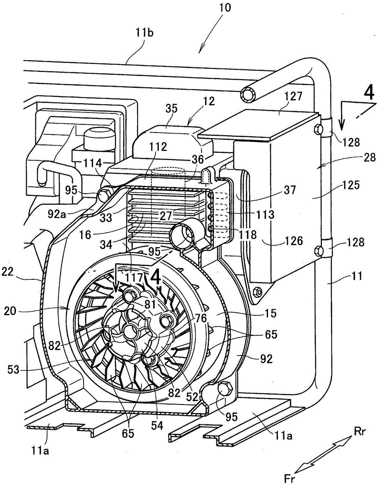
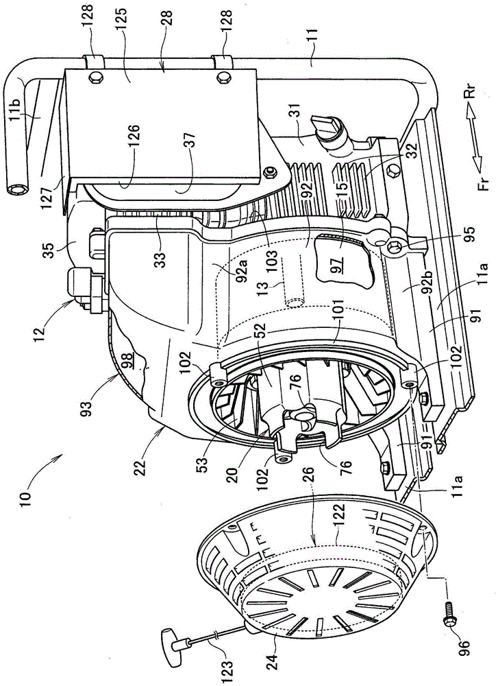
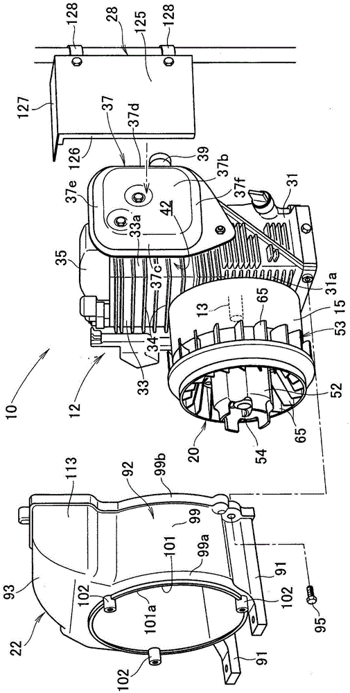
[0039] Such as figure 1 , figure 2 As shown, the engine-driven generator 10 has: the engine 12 installed on the bottom 11a of the frame 11; the power generation unit 15 arranged in front of the engine 12; the cooling fan 20 connected to the drive shaft of the power generation unit 15; and the cover The fan 20 and the fan cover 22 of the power generation unit 15 are cooled.

[0040] Further, the engine-driven generator 10 has: a recoil cover 24 installed on the fan cover 22; a recoil starter 26 installed on the recoil cover 24; 27; and the muffler protector 28 that protects the exhaust muffler 37.

[0041] The frame 11 is formed in a substantially rectangular shape along the engine 12 , the exhaust muffler 37 and the cooling fan 20 by pipe members. The engine 12 , the exhaust muffler 37 and the cooling fan 20 are held in a steady state by the frame 11 .

[0042] In addition, the engine generator 1...


PUM


Abstract

The invention provides an engine-driven generator which is capable of achieving down-sizing of the engine-driven generator while securing proper cooling of a cylinder block and an exhaust muffler. The engine-driven generator (10) includes an exhaust muffler (37) disposed adjacent to a lateral side (33a) of a cylinder block (33), a fan cover (22) having an air outlet (116) arranged to face the exhaust muffler (37) and the cylinder block (33), the fan cover (22) being configured to guide cooling air from a cooling fan (20) directly to the air outlet (116), and an opening area-adjustment member (27) provided on a muffler blow-off port (118) of the air outlet (116) for adjusting an opening area of the muffler blow-off port (118).

Description

technical field [0001] The present invention relates to an engine-driven generator that is provided with an exhaust muffler near a cylinder block of an engine and drives a power generating unit by the engine. Background technique [0002] An engine-driven generator is known in which a cooling fan is provided on one side of the engine (hereinafter, referred to as the front side), and an exhaust muffler is provided on the other side of the engine (hereinafter, referred to as the rear side). The cooling air sent from the cooling fan cools the engine and exhaust muffler. [0003] Specifically, the engine (in particular, the cylinder block) is cooled by cooling air sent from a cooling fan, and the exhaust muffler is cooled by the cooling air after cooling the engine (for example, refer to Patent Document 1). [0004] prior art literature [0005] patent documents [0006] Patent Document 1: WO2008 / 032414 Publication [0007] However, the engine-driven generator of Patent Docu...

Claims


Application Information

Patent Timeline
Patent Type & Authority Applications(China)
IPC IPC(8): F01P5/06F01P1/02F01P1/06F01P7/02F02B63/04
CPCF01N13/002F01N1/00F01N2260/022F01N2260/20F01N2590/10F01P1/06F02B63/04F02B63/044F01P5/06F01P1/02F01P7/02F01P2001/023
Inventor 高桥祐树加势拓男下园和树箭内几代美
Owner HONDA MOTOR CO LTD
Learn More