Conveyor support

A conveyor and support plate technology, applied in the direction of conveyor, transportation and packaging, can solve the problems of inability to achieve complete contact between the conveyor unit and the beam, and the single function of the conveyor bracket, achieving rich functions, simple process, easy climbing The effect of slope conveying

Inactive Publication Date: 2016-10-12
JIANGSU HUAZHANG LOGISTICS TECH CO LTD
View PDF9 Cites 6 Cited by
  • Summary
  • Abstract
  • Description
  • Claims
  • Application Information

AI Technical Summary

Problems solved by technology

[0004] Aiming at the deficiencies of the above-mentioned prior art, the purpose of the present invention is to provide a conveyor support to solve the problems in the prior art that the conveyor support has a single function and cannot realize the complete contact between the conveyor unit and the beam.

Method used


Image

  • Conveyor support
  • Conveyor support
  • Conveyor support

Examples


Embodiment Construction

[0021] In order to facilitate the understanding of those skilled in the art, the present invention will be further described below in conjunction with the embodiments and accompanying drawings, and the contents mentioned in the embodiments are not intended to limit the present invention.

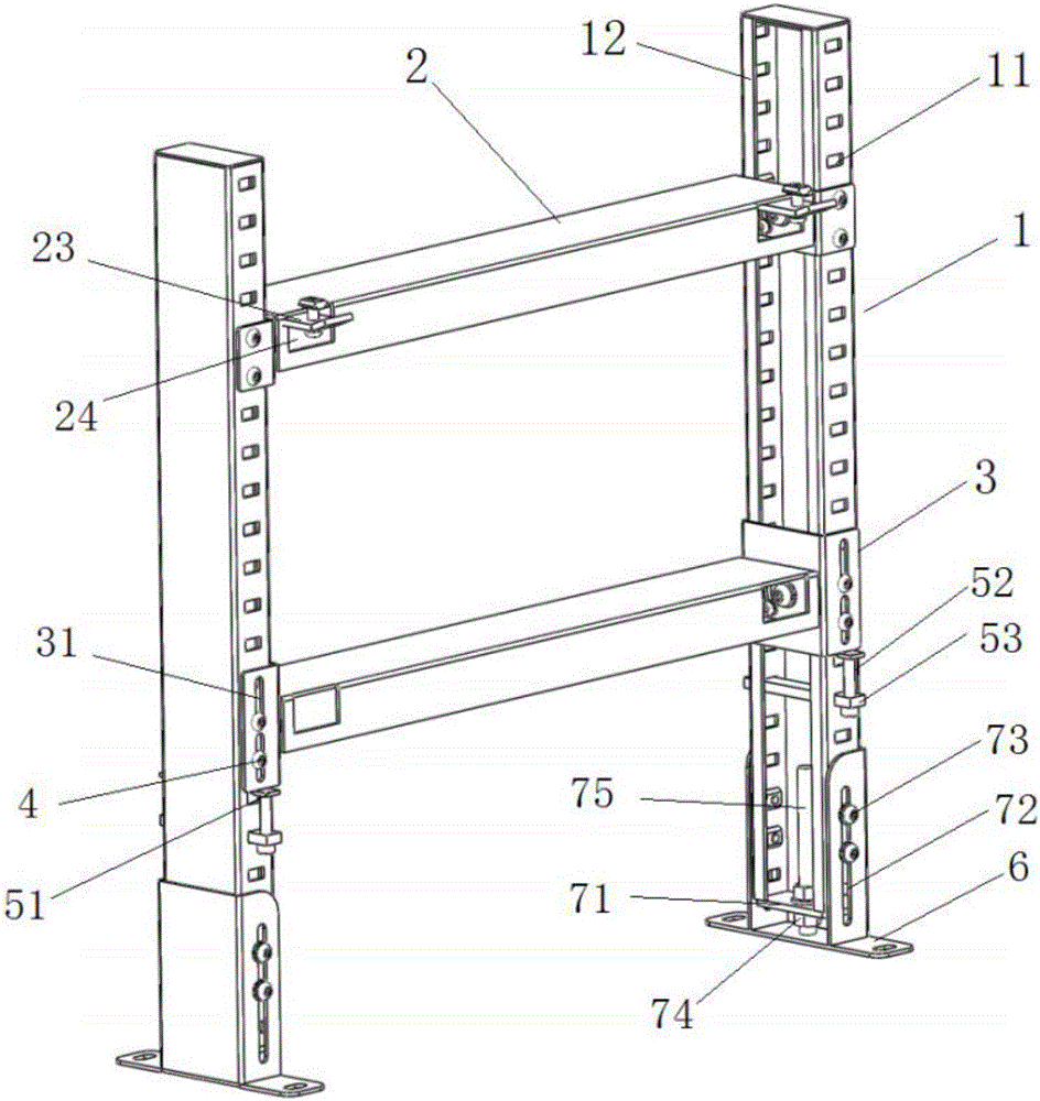
[0022] refer to figure 1 As shown in Figure 3, a conveyor bracket of the present invention is used to support and fix the conveyor, and it includes: a column 1, a connector 2 and a crossbeam 3, at least one beam 3 is arranged between two columns 1, and the crossbeam 3 is connected with the column 1 through the connecting piece 2, wherein,

[0023] The column 1 is provided with a plurality of symmetrical first fixing holes 11 on both sides; the two sides of the column 1 are designed to be bent, and the ends of the two sides are respectively provided with folded edges 12, so that the two sides form a space respectively. Cavities to accommodate square nuts;

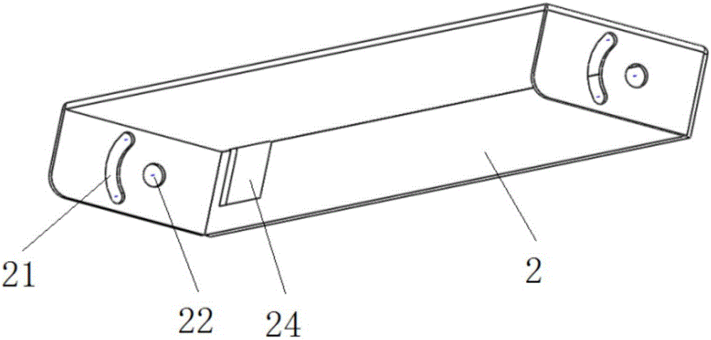
[0024] The crossbeam 2 is provide...


PUM


Abstract

The invention discloses a conveyor support which comprises two stand columns, connecting parts and at least one cross beam. The at least one cross beam is arranged between the two stand columns, and the cross beams and the stand columns are connected through the connecting parts. The two side faces of each stand column are provided with a plurality of symmetrical first fixing holes. The two end faces of each cross beam are each provided with an arc sliding groove and a second fixing hole. The two end faces of each connecting part are each provided with third fixing holes. The connecting parts are fixed to the corresponding stand columns by connecting the third fixing holes with the first fixing holes through fixing parts. A fourth fixing hole and a fifth fixing hole are further formed in the side face, making contact with one end face of the corresponding cross beam, of each connecting part, and are matched with the corresponding arc sliding groove and the corresponding second fixing hole through fixing parts correspondingly. The angles of the cross beams are changed through sliding of the fixing parts in the arc sliding grooves. According to the conveyor support, the problems that in the prior art, a conveyor support is simplex in function, and complete contact between conveyor units and the cross beams cannot be achieved are solved.

Description

technical field [0001] The invention relates to the technical field of logistics conveyors, and in particular refers to a conveyor bracket capable of freely lifting the conveyor and changing a certain angle. Background technique [0002] In the production process, materials, semi-finished products or finished products are often transported between different workstations or production and processing lines for many times. If manual transport is used, it will waste a lot of time and human resource costs, and also reduce production efficiency. What's more, some items are inconvenient to use manual handling. [0003] Conveyor is a material handling machine that continuously conveys materials on a certain line. The conveyor can carry out horizontal conveying, inclined conveying, and can also form a space automatic conveying line. The automatic conveying line is generally fixed. The conveyor has a large conveying capacity, a long transportation distance, and can complete several p...

Claims


Application Information

Patent Timeline
IPC IPC(8): B65G21/12
CPCB65G21/12
Inventor 华聚良
Owner JIANGSU HUAZHANG LOGISTICS TECH CO LTD
Why Eureka
Try Eureka