Aircraft with air crash lifesaving function

A functional and air disaster technology, applied in the field of aircraft structure, to achieve the effect of reducing both human and property losses

Inactive Publication Date: 2016-10-12
冯政尧
View PDF9 Cites 4 Cited by
  • Summary
  • Abstract
  • Description
  • Claims
  • Application Information

AI Technical Summary

Problems solved by technology

[0004] However, the nose of the aircraft is where the people and equipment that control the flight of the aircra

Method used


Image

  • Aircraft with air crash lifesaving function
  • Aircraft with air crash lifesaving function
  • Aircraft with air crash lifesaving function

Examples


Embodiment 1

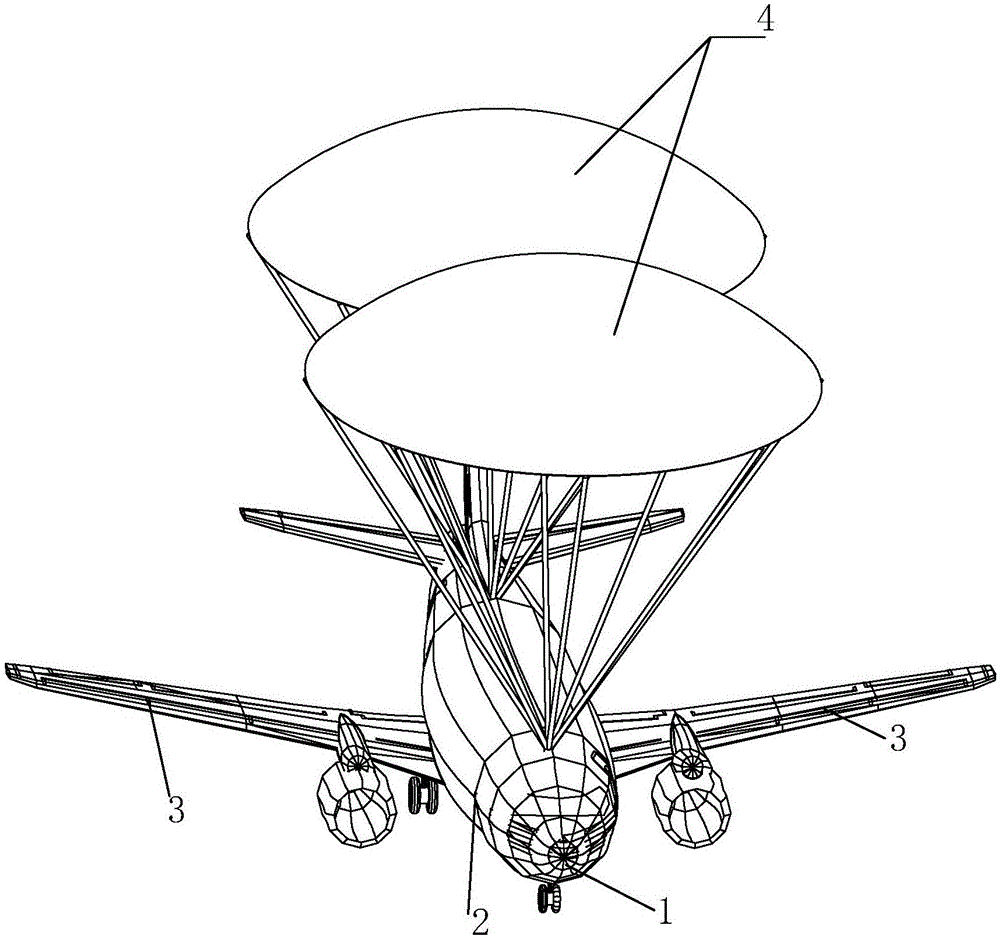
[0039] An aircraft with air crash rescue functions, such as figure 1 As shown in , its structure is the same as that of a general aircraft, including a nose 1, a cabin 2 integrally formed with the nose 1, and wings 3 symmetrically arranged on both sides of the cabin 2.

[0040] A plug-in assembly 6 is provided between the wing 3 and the cabin 2 to form a detachable connection. During normal flight, the plug-in assembly 6 connects the wing 3 and the cabin 2, and the wing 3 normally drives the aircraft to fly; When removing the wing 3, the plug assembly 6 is opened, so that the wing 3 and the cabin 2 are separated from each other under the effect of external force.

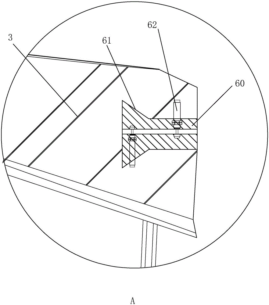
[0041] Specifically, such as Figures 2 to 3As shown in , the plug-in assembly 6 includes a pair of claws 60, a slot 61 matched therewith, and a driving member 62 arranged between the pair of claws 60, wherein the driving member 62 can be a hydraulic cylinder or an air cylinder, etc. , taking the hydraulic cylinde...

Embodiment 2

[0050] An aircraft with air disaster rescue function, the difference from Embodiment 1 is that when a pair of claws 60 are pressed into the groove 61, a gap is formed between the claws 60 as the hydraulic pressure of the driving member 62. When the piston rod of the cylinder stretches into this gap, the gap between a pair of claws 60 will be filled up. At this time, because the gap is filled up by the piston rod, the two claws 60 are pressed against in the draw-in groove 61.

Embodiment 3

[0052] A kind of aircraft with air disaster rescue function, and the difference in embodiment 1 is: as Figures 5 to 6 As shown in , viewed along the top surface of the wing 3, the cross-sectional shape of the slot 61 is dovetail-shaped. When this connection structure is adopted, when the driving member 62 between the pair of claws 60 is connected together, the pair of claws 60 must be able to withdraw from the slot 61, so that the wing 3 is arranged along the point direction of the plug assembly 6. Rear rotation out of cabin 2.

[0053] In order to prevent the claw 60 from interfering with the slot 61 during the backward rotation of the wing 3, the claw 60 and the slot 61 are arranged along the extension direction of the wing 3 from the cabin 2 to its two sides, so that the clip The claw 60 can be disengaged from the slot 61 smoothly.

[0054] Because the wing 3 rotates backwards and disengages the process of the cabin 2, in order to prevent the disengaged wing 3 from reach...


PUM


Abstract

The invention discloses an aircraft with an air crash lifesaving function. The aircraft comprises a nose, a passenger cabin and wings arranged on the left and right sides of the passenger cabin, wherein the wings are detachably connected with the passenger cabin through insertion connecting components; each insertion connecting component comprises a pair of clamping jaws, a clamping groove matched with the clamping jaws and a driving part for driving the clamping jaws to be opened and pressed against the clamping groove or folded to be separated from the clamping groove; parachutes capable of being unfolded after the wings are separated and reverse jet devices for reducing the falling speed of the passenger cabin are arranged in the passenger cabin; at least one inflation unit for cushioning the falling impact force of the passenger cabin and the nose is also arranged at the bottom of the passenger cabin. In case of an aircraft accident, the wings are separated from the other positions of the aircraft in the first place to save pilots and important control elements in the nose on the basis of saving passengers in the passenger cabin, so that the passengers on the aircraft with such an accident and most of important parts of the aircraft are safely landed, and air crash loss is reduced.

Description

technical field [0001] The invention relates to an aircraft structure capable of rescuing all persons on board the aircraft in the event of an air disaster and having an air disaster life-saving function. Background technique [0002] Airplanes are the most important and fastest means of transportation in modern times. Analyzing from the structural point of view, airplanes should also be the means of transportation with the highest safety factor. However, since the operating area of ​​the aircraft is high altitude, there are many unpredictable factors. Even if the aircraft is fully and meticulously inspected before each flight, it is still impossible to avoid air crashes caused by various factors. And because the plane operates at a high altitude, once an air crash occurs, the people in the plane, especially the ordinary passengers in the passenger plane, rely on the guidance, comfort and guidance of the flight attendants, and still cannot make the passengers have the abilit...

Claims


Application Information

Patent Timeline
IPC IPC(8): B64C1/32B64D17/80B64D45/04
CPCB64C1/32B64D17/80B64D25/12B64D45/04
Inventor 冯政尧
Owner 冯政尧
Why Eureka
Try Eureka