Die for cutting thin sheet and method for cutting thin sheet

A thin plate and mold technology, applied in welding/cutting auxiliary equipment, welding/welding/cutting items, manufacturing tools, etc., can solve the problems of inability to cut thin plates, decline in the finish of thin plate sections, and sinking of thin plates

Inactive Publication Date: 2016-10-12
四川新远宏机械设备有限公司
View PDF5 Cites 8 Cited by
  • Summary
  • Abstract
  • Description
  • Claims
  • Application Information

AI Technical Summary

Problems solved by technology

When the laser cuts the thin plate, the pressure gas will act on the thin plate, which will cause the thin plate to sink, deform, and cause displacement, resulting in a decrease in the cross-section finish of the cut thin plate and low cutting accuracy.
Moreover, this cutting method cannot cut plates with a thickness below 0.5 mm
It can be seen that in the existing thin plate cutting, there are the following technical problems: the thin plate will sink and deform during the cutting process, resulting in low cutting accuracy; and it is impossible to cut thin plates with a thickness below 0.5 mm

Method used


Image

  • Die for cutting thin sheet and method for cutting thin sheet

Examples


Embodiment Construction

[0024] The technical solutions of the present invention will be clearly and completely described below in conjunction with the accompanying drawings of the present invention. Apparently, the described embodiments are only some of the embodiments of the present invention, not all of them. Based on the embodiments of the present invention, all other embodiments obtained by persons of ordinary skill in the art without creative efforts fall within the protection scope of the present invention.

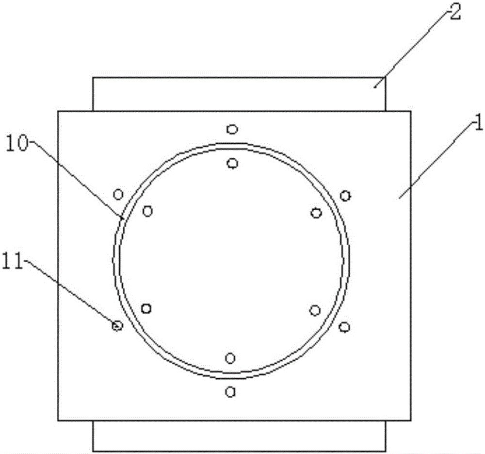
[0025] combine figure 1 As shown, the present invention provides a mold for thin plate cutting, including a tire plate 1, which is a square steel plate. Cutting grooves 10 are provided on the upper surface of the tire plate 1, and the shape of the cutting grooves 10 corresponds to the shape of the workpiece to be processed. In this embodiment, the cutting grooves 10 are circular. The width of the cutting groove 10 can be in the range of 0.3-5 mm, so as to ensure that the width can meet th...


PUM

PropertyMeasurementUnit
widthaaaaaaaaaa
thicknessaaaaaaaaaa
surface smoothnessaaaaaaaaaa

Abstract

The invention provides a mold for thin plate cutting, which includes a tire board, cutting grooves are provided on the upper surface of the tire board, and the shape of the cutting grooves corresponds to the shape of workpieces to be processed. Magnets are arranged on the upper surface of the tire plate. When cutting, the thin plate is placed on the upper surface of the tire plate, and the cutting path of the laser follows the cutting groove on the tire plate. When the pressure gas acts on the thin plate, the entire thin plate can be supported by the tire plate, and there will be no sinking and deformation of the thin plate. The thin plate is firmly fixed on the tire plate through the magnet, which solves the problem of displacement of the thin plate during the cutting process and improves the machining accuracy of the cutting workpiece. The invention also provides a thin plate cutting method, which includes making cutting grooves of the mold, fixing the thin plate on the tire plate through magnets, and cutting along the cutting grooves with laser light.

Description

technical field [0001] The invention relates to the technical field of laser cutting processing, in particular to a mold for thin plate cutting and a thin plate cutting method. Background technique [0002] The working platform of the existing laser equipment is a hollow structure. The four sides of the workbench are supporting surfaces, and the middle is a hollow part. When cutting a thin plate, place the thin plate directly on the working platform so that the thin plate is supported by the supporting surface. Control the laser speed to cut the thin plate in the hollow part. When the laser cuts the thin plate, the pressure gas will act on the thin plate, which will cause the thin plate to sink, deform, and cause displacement, resulting in a decrease in the cross-section finish of the cut thin plate and low cutting accuracy. Moreover, this cutting method cannot cut plates with a thickness below 0.5 mm. It can be seen that the following technical problems exist in the exi...

Claims


Application Information

Patent Timeline
Patent Type & Authority Applications(China)
IPC IPC(8): B23K37/04B23K26/70B23K26/38B23K101/18
CPCB23K37/0408B23K26/38B23K26/702B23K2101/18
Inventor 蒲书元蒲书忠邹世华
Owner 四川新远宏机械设备有限公司
Why Eureka
Try Eureka