A tubular welding rod for laser cladding and gas welding and its preparation method
A laser cladding and welding rod technology, applied in welding equipment, welding media, manufacturing tools, etc., can solve problems such as difficulty in using alone, and achieve the effect of eliminating gas protection, high hardness, and reducing cladding layer defects
- Summary
- Abstract
- Description
- Claims
- Application Information
AI Technical Summary
Problems solved by technology
Method used
Image
Examples
Embodiment 1
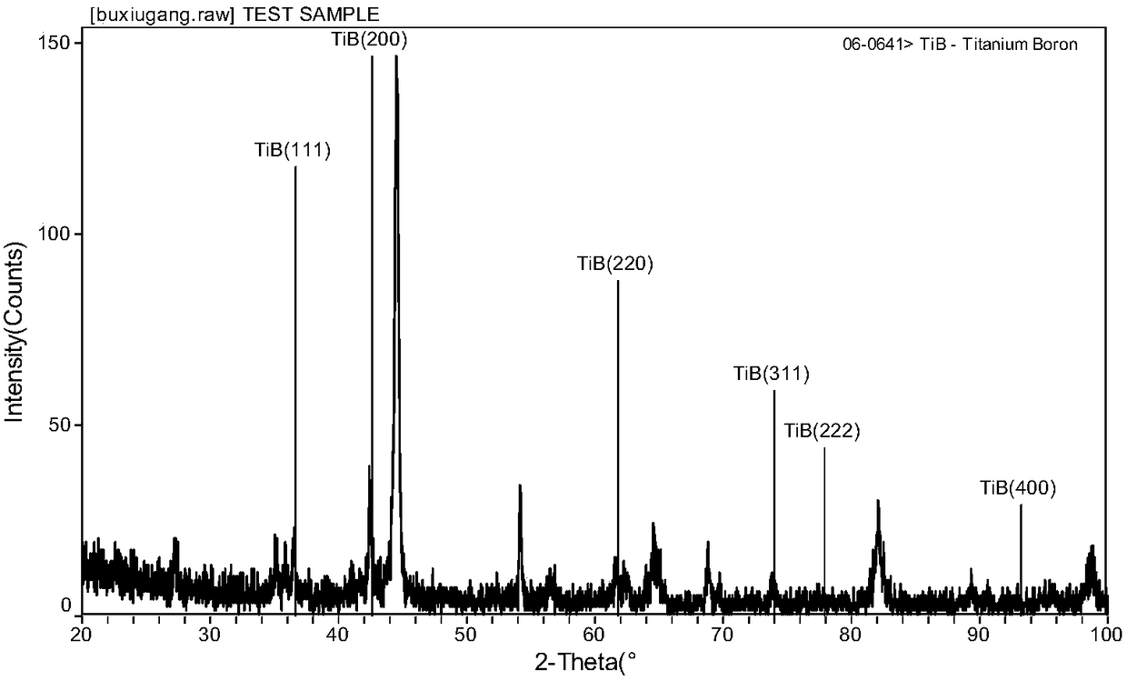
[0040] A tubular electrode for laser cladding and gas welding, consisting of a metal tube and a welding core located in the metal tube; the welding core is made by mixing 60g Co, 80g Ni, 10g WC and 850g face-centered cubic TiB powder , the particle size is -200 mesh; the metal tube is A3 low carbon steel.
[0041] The metal tube is a cylindrical or rectangular tube.
[0042] A preparation method of a tubular electrode for laser cladding and gas welding, comprising the following specific steps:
[0043] A. Preparation of solder core mixture
[0044] Accurately weigh 60g Co powder, 80g Ni powder, 10g WC powder and 850g face-centered cubic TiB powder, and mix them with ethanol at a weight ratio of 1:1 in a ball mill as a solder core material for use; the ball mill rotates at 300rpm , the ball milling time is 100 hours, the grinding ball material is stainless steel, and its diameter is 50mm;
[0045] B, electrode preparation
[0046] After the ethanol is volatilized, the spare...
Embodiment 2
[0050] Laser Cladding on Mn13 Steel Plate Using Welding Rod Prepared in Example 1
[0051] CO 2Laser equipment, the output power is 5kW, the spot diameter is 5mm, the laser mode is low-order mode, the base material is a rolled Mn13 steel plate, the steel plate is 1800mm long, 360mm wide and 12mm thick. A full-length groove is opened every 150mm on the steel plate, and the width and depth of the groove are 5.5mm and 5mm respectively. The electrode is implanted into the groove, and the material of the electrode tube is 08-Z steel. Put the Mn13 steel plate on the worktable, the worktable can move relative to the laser beam, and use the laser beam to align the welding rod embedded in the groove, so that the worktable moves relative to the laser beam at a speed of 10mm / s. After the cladding is complete, the steel plate is moved so that the laser is aimed at another electrode. By repeating the above process, multiple laser cladding layers are obtained on the steel plate, and the ...
Embodiment 3
[0053] Laser cladding on iron-based powder metallurgy materials using the electrode prepared in Example 1
[0054] CO 2 The output power of the laser equipment is 5 kW, the spot diameter is 5 mm, the laser mode is low-order mode, the base material is iron-based powder metallurgy material, the composition is Fe-2Cu-0.7C (wt%), and it is sintered at 1200 ℃ for 2 hours. , the density is 7.0g / cm 3 , the sample size is 10×10×65mm, and the scanning speed is 10mm / s. The properties of the obtained cladding layer are: depth 1mm, microhardness HV700, chemical composition of the cladding layer such as Figure 3a-Figure 3e shown. The presence of Ti element in the cladding layer indicates that the laser cladding layer contains face-centered cubic TiB phase.
PUM
| Property | Measurement | Unit |
|---|---|---|
| length | aaaaa | aaaaa |
| density | aaaaa | aaaaa |
| length | aaaaa | aaaaa |
Abstract
Description
Claims
Application Information
 - R&D
- Intellectual Property
- Life Sciences
- Materials
- Tech Scout
- Unparalleled Data Quality
- Higher Quality Content
- 60% Fewer Hallucinations
Browse by: Latest US Patents, China's latest patents, Technical Efficacy Thesaurus, Application Domain, Technology Topic, Popular Technical Reports.
© 2025 PatSnap. All rights reserved.Legal|Privacy policy|Modern Slavery Act Transparency Statement|Sitemap|About US| Contact US: help@patsnap.com


