CT imaging system
A technology of CT imaging and rotating arm, which is applied in computerized tomography scanners, echo tomography, etc., can solve problems such as cumbersome detection steps and complex mechanical structures, and achieve the effects of shortening detection time, simplifying equipment structure, and achieving technical effects
- Summary
- Abstract
- Description
- Claims
- Application Information
AI Technical Summary
Problems solved by technology
Method used
Image


Examples
Embodiment 1
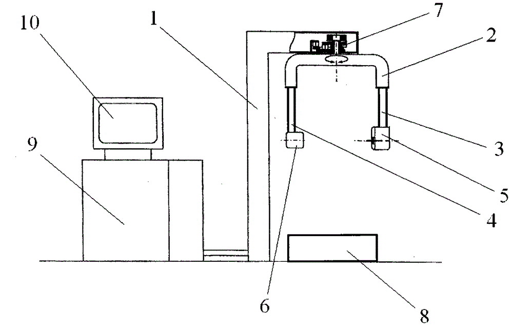
[0026] A CT imaging system, characterized in that it includes a fixed stand 1, a rotating arm 2, a first telescopic arm 3, a second telescopic arm 4, an X-ray emitter 5, an X-ray receiver 6, a motor 7, and a detection table 8 , a signal processor 9, a display screen 10, wherein the signal processor 9 is connected to the display screen 10 and the X-ray receiver 6 through lines respectively, the motor 7 is connected to the inside of the fixed stand 1, and the rotating arm 2 is connected to the lower end of the motor 7, the second A telescopic arm 3 and a second telescopic arm 4 are located at both ends of the rotating arm 2 and extend downwards, the X-ray emitter 5 is fixedly connected to the lower end of the first telescopic arm 3, and the X-ray receiver 6 is fixedly connected to the second telescopic arm 4 At the lower end, the detection platform 8 is fixedly placed below the rotating arm 2; meanwhile, the X-ray receiver 6 includes a main substrate 61 and several detection unit...
Embodiment 2
[0030] A CT imaging system, characterized in that it includes a fixed stand 1, a rotating arm 2, a first telescopic arm 3, a second telescopic arm 4, an X-ray emitter 5, an X-ray receiver 6, a motor 7, and a detection table 8 , a signal processor 9, a display screen 10, wherein the signal processor 9 is connected to the display screen 10 and the X-ray receiver 6 through lines respectively, the motor 7 is connected to the inside of the fixed stand 1, and the rotating arm 2 is connected to the lower end of the motor 7, the second A telescopic arm 3 and a second telescopic arm 4 are located at both ends of the rotating arm 2 and extend downwards, the X-ray emitter 5 is fixedly connected to the lower end of the first telescopic arm 3, and the X-ray receiver 6 is fixedly connected to the second telescopic arm 4 At the lower end, the detection platform 8 is fixedly placed below the rotating arm 2; meanwhile, the X-ray receiver 6 includes a main substrate 61 and several detection unit...
Embodiment 3
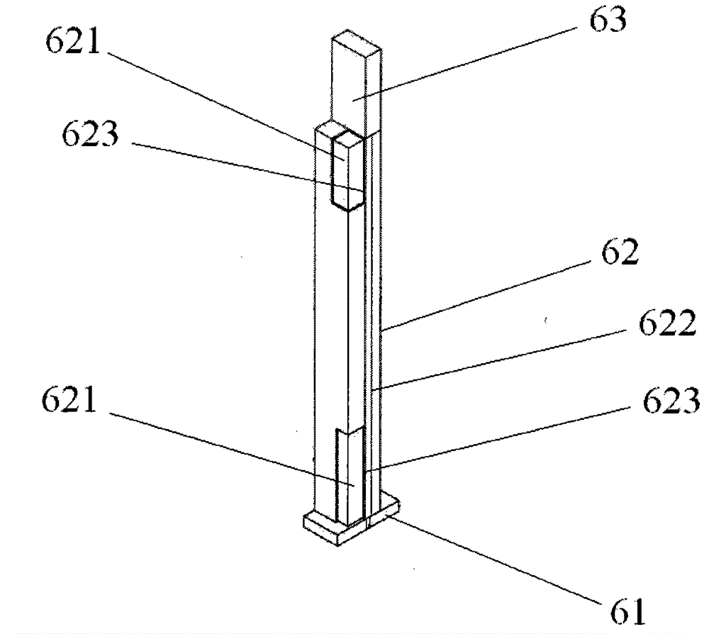
[0034] A CT imaging system is characterized in that it includes a fixed stand 1, a rotating arm 2, a first telescopic arm 3, a second telescopic arm 4, an X-ray emitter 5, an X-ray receiver 6, a motor 7, and a detection table 8 , signal processor 9, display screen 10, wherein signal processor 9 is connected with display screen 10, X-ray receiver 6 by line respectively, motor 7 is connected in fixed platform 1 inside, and rotating arm 2 is connected in motor 7 lower ends, the first A telescopic arm 3 and a second telescopic arm 4 are located at both ends of the rotating arm 2 and extend downwards, the X-ray emitter 5 is fixedly connected to the lower end of the first telescopic arm 3, and the X-ray receiver 6 is fixedly connected to the second telescopic arm 4 At the lower end, the detection platform 8 is fixedly placed below the rotating arm 2; meanwhile, the X-ray receiver 6 includes a main substrate 61 and several detection units 62 uniformly fixed on the main substrate 61, a...
PUM
 Abstract
Description
Claims
Application Information
 - Generate Ideas
- Intellectual Property
- Life Sciences
- Materials
- Tech Scout
- Unparalleled Data Quality
- Higher Quality Content
- 60% Fewer Hallucinations
Browse by: Latest US Patents, China's latest patents, Technical Efficacy Thesaurus, Application Domain, Technology Topic, Popular Technical Reports.
© 2025 PatSnap. All rights reserved.Legal|Privacy policy|Modern Slavery Act Transparency Statement|Sitemap|About US| Contact US: help@patsnap.com