
Low-frequency offset three-phase multi-inverter parallel operation control method under micro-grid island

A technology of three-phase inverter and multi-inverter, which is applied in the direction of single-network parallel feeding arrangement, AC network circuit, reducing/preventing power oscillation, etc. Problems such as small voltage and frequency fluctuations

Active Publication Date: 2016-09-28
HUNAN UNIV
View PDF2 Cites 10 Cited by
  • Summary
  • Abstract
  • Description
  • Claims
  • Application Information

AI Technical Summary

Problems solved by technology

Because there is no voltage clamping of the large grid in the microgrid island, there is no common phase reference between the inverters, which makes it difficult for the current output by each inverter to be in phase
In addition, due to the difference in the parameters of the feeder line, the amplitude of the output current of the inverter cannot be distributed in proportion to the rated capacity of the micro-source
The existing micro-grid island multi-inverter control method is mainly based on droop control, and the output of the inverter is controlled as a voltage source. The disadvantage of this method is that the circulation suppression effect is affected by the parameters of the feeder line, and a good circulation cannot be guaranteed at the same time. suppression effect with small voltage and frequency fluctuations

Method used


Image

  • Low-frequency offset three-phase multi-inverter parallel operation control method under micro-grid island
  • Low-frequency offset three-phase multi-inverter parallel operation control method under micro-grid island
  • Low-frequency offset three-phase multi-inverter parallel operation control method under micro-grid island

Examples


Embodiment Construction

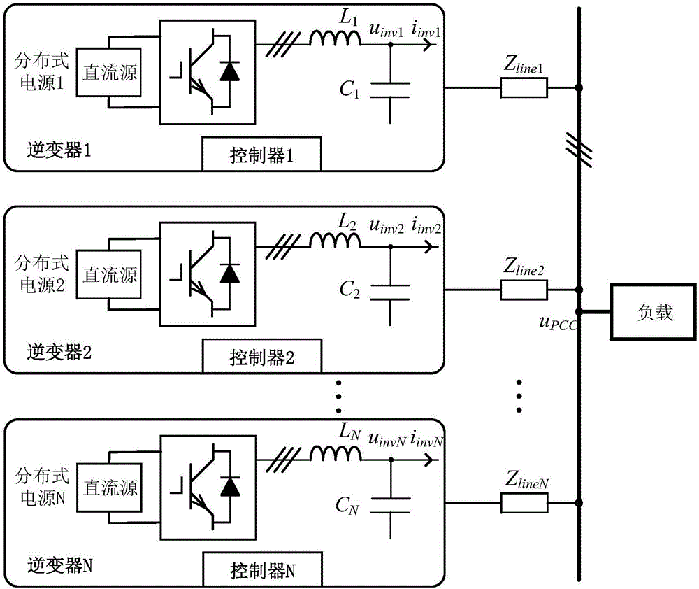
[0033] figure 1 It is a structural diagram of a three-phase multi-inverter parallel operation system under a microgrid island in an embodiment of the present invention, including multiple three-phase inverter systems, feeders, busbars, and loads. The three-phase inverter system includes distributed power supplies, Three-phase inverter bridge, LC filter, controller. u PCC is the bus voltage, i inv1 i inv2 i invNis the output current of inverter 1, 2, N, u inv1 , u inv2 , u invN is the output filter capacitor voltage of inverter 1, 2, N, L 1 , L 2 , L N is the filter inductance of inverter 1, 2, N, C 1 、C 2 、C N is the filter capacitor of inverter 1, 2, N, Z line1 ,Z line2 ,Z lineN is the feeder impedance of inverters 1, 2, and N connected to the bus, and N represents the total number of inverters in the microgrid.

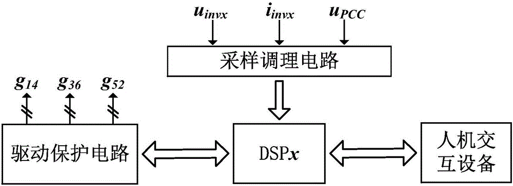
[0034] figure 2 It is the structural diagram of the inverter controller control circuit in the embodiment of the present invention, including DSP ...


PUM


Abstract

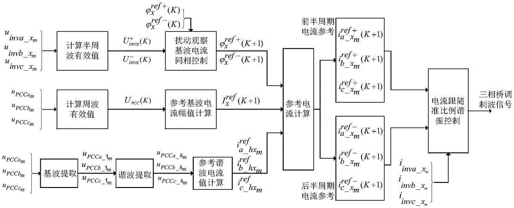
The invention discloses a low-frequency offset three-phase multi-inverter parallel operation control method under a micro-grid island. Each inverter and an LC filter thereof under the micro-grid island are controlled to be voltage-controlled current sources; a reference frequency of fundamental current output by each inverter is a rated value; a reference phase can be obtained through a disturbance observation-based maximum output voltage tracking method; a reference amplitude of the fundamental current output by each inverter is obtained through common bus-based feedback proportional control; distribution of output current of each inverter according to the capacity proportion can be achieved by reasonably setting a proportion coefficient and a voltage amplitude on a micro-grid bus is controlled to be close to the rated value; a harmonic current reference output by each inverter is obtained through bus harmonic voltage feedback control; and quasi proportional resonant control in a static coordinate system is adopted as current tracking control of each inverter. According to the low-frequency offset three-phase multi-inverter parallel operation control method under the micro-grid island, the influence of the difference between line parameters on equal division of output current of each inverter is overcome, the frequency of the voltage in the micro-grid operation process is relatively stable and the influence of voltage frequency fluctuation on a load is reduced.

Description

technical field [0001] The invention relates to the technical field of three-phase inverter control, in particular to the field of parallel operation control of three-phase multi-inverters under micro-grid islands. Background technique [0002] There are two typical operation modes of the microgrid. Under normal circumstances, the microgrid and the large grid are connected to the grid, which is called the grid-connected mode; when a fault is detected in the large grid or the power quality does not meet the requirements, the microgrid will be disconnected from the large grid Running in island mode can ensure the continuous power supply of important loads in the event of a large grid failure. In addition, most distributed power sources in the microgrid need to be integrated into the microgrid through inverters. The stable parallel operation of the inverters will greatly improve the overall capacity and reliability of the microgrid system. Therefore, a key control technology o...

Claims


Application Information

Patent Timeline
IPC IPC(8): H02J3/46H02J3/24
CPCH02J3/24H02J3/381H02J3/388H02J3/46
Inventor 罗安伍文华陈燕东周小平杨苓黎燕怀坤山程石
Owner HUNAN UNIV
Learn More