
A Static Synchronous Series Compensation Device Combined with Series Compensation and Converter

A series compensation and static synchronous technology, applied in the direction of circuit devices, AC network circuits, flexible AC transmission systems, etc., can solve the problems of flexibility and action speed that cannot meet precise adjustment, do not have capacity and price advantages, and have high insulation requirements. Achieve continuous and rapid two-way adjustment capability, improve dynamic response performance, and reduce the effect of insulation level

Active Publication Date: 2018-01-19
GLOBAL ENERGY INTERCONNECTION RES INST CO LTD +1
View PDF3 Cites 0 Cited by
  • Summary
  • Abstract
  • Description
  • Claims
  • Application Information

AI Technical Summary

Problems solved by technology

[0004] Traditional capacitors and reactors are used as line series compensation, and their flexibility and action speed cannot meet the requirements of precise adjustment; traditional controllable series compensation has high requirements for insulation and general economy; conventional static synchronous series compensators have flexible and excellent control functions, but Its promotion and use in the power system does not have capacity and price advantages

Method used


Image

  • A Static Synchronous Series Compensation Device Combined with Series Compensation and Converter
  • A Static Synchronous Series Compensation Device Combined with Series Compensation and Converter
  • A Static Synchronous Series Compensation Device Combined with Series Compensation and Converter

Examples


Embodiment 1

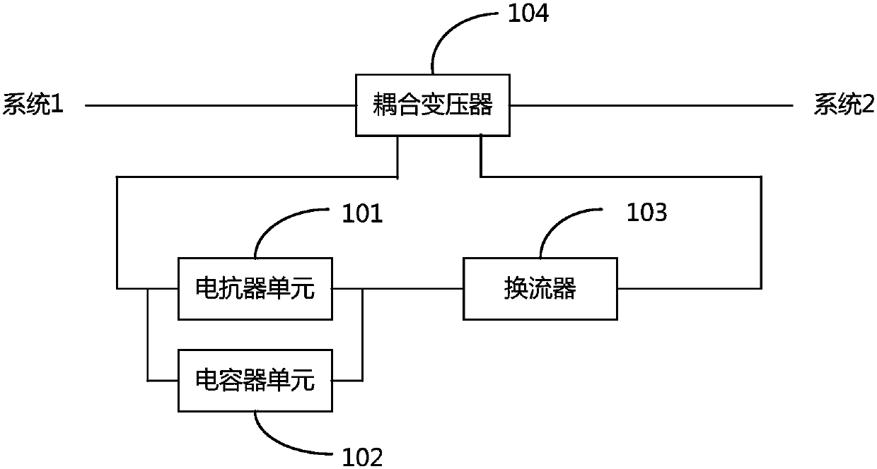
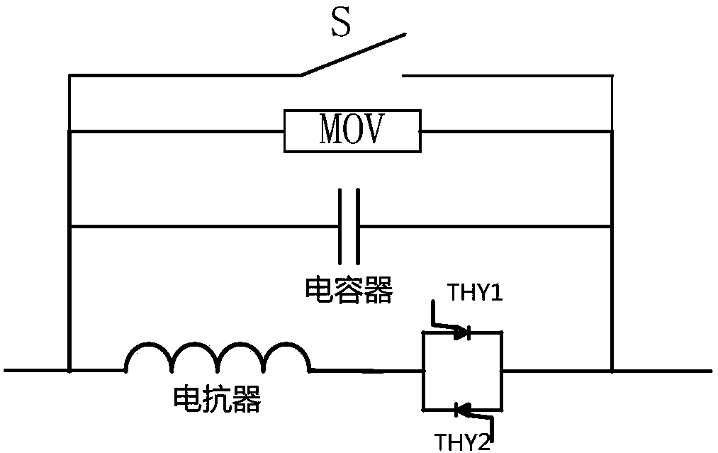
[0043] Embodiment 1: After changing the firing angle of the thyristor in the thyristor bidirectional switch, the equivalent reactance of the reactor unit 101 is smaller than the equivalent capacitive reactance of the capacitor unit 102, then the static synchronous series compensation device works in the capacitive compensation mode, and the transmission line Perform capacitive compensation.

Embodiment 2

[0044] Embodiment 2: After changing the firing angle of the thyristor in the thyristor bidirectional switch, the equivalent reactance of the reactor unit 101 is greater than the equivalent capacitive reactance of the capacitor unit 102, then the static synchronous series compensation device works in the inductive compensation mode, and the power transmission line is Sensual compensation.

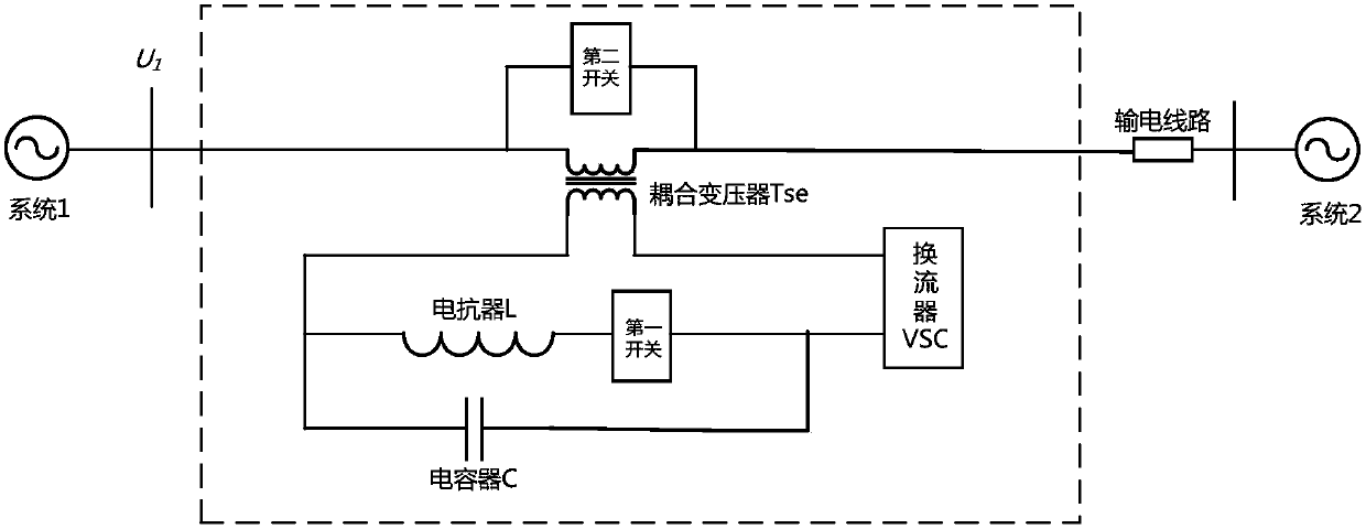
[0045] In the embodiment of the present invention, the second switch includes any one of a circuit breaker, an isolating switch and a power electronic switch or any two switches connected in parallel, and the second switch is used to control the input and withdrawal of the coupling transformer. Wherein, the two types of switches connected in parallel may be that the circuit breaker is connected in parallel with the isolating switch, the circuit breaker is connected in parallel with the power electronic switch, and the isolating switch is connected in parallel with the power electronic switch....


PUM


Abstract

The invention provides a static synchronous series compensation device combined with a series compensation and a converter, including a converter, a coupling transformer, an inductive offset module and / or a capacitive offset module; the inductive offset module and the inverter The converters are connected in parallel with one winding of the coupling transformer, and the other winding of the coupling transformer is connected with the transmission line; the capacitive offset module is connected with the converter in parallel and connected in parallel with one winding of the coupling transformer. The other winding of the coupling transformer is connected to the transmission line; the inductive offset module includes a reactor unit, and the capacitive offset module includes a capacitor unit connected in series and a first switch. Compared with the prior art, the present invention provides a static synchronous series compensation device combined with a series compensation and a converter, which can be used in transmission lines or distribution lines to perform capacitive or inductive adjustments to improve line transmission capacity. Improve system stability, control line flow, enhance system damping, and reduce costs.

Description

technical field [0001] The invention relates to the technical field of power electronics, in particular to a static synchronous series compensation device combining series compensation and a converter. Background technique [0002] Series compensation devices are often used on transmission lines to increase the stable transmission capacity of the system and improve the electrical parameters of the line. On long transmission lines, series capacitors can be used to counteract the effects of line inductance. Since the series capacitor and the line inductance are connected in series, the current is the same, the voltage of the capacitor lags the current by 90 degrees, and the voltage of the inductor leads the current by 90 degrees, so the capacitor voltage and the inductor voltage are exactly opposite and can cancel each other out. Thereby shortening the equivalent electrical distance and improving the power transmission capacity and voltage stability of the power grid. [000...

Claims


Application Information

Patent Timeline
Patent Type & Authority Patents(China)
IPC IPC(8): H02J3/00
CPCY02E40/10
Inventor 陆振纲尉志勇宋洁莹戴朝波邓占锋赵国亮蔡林海
Owner GLOBAL ENERGY INTERCONNECTION RES INST CO LTD
Learn More