A detection device and method for a carrier envelope phase signal

A carrier envelope phase and detection device technology, applied in the fields of fiber laser and optoelectronic physics, can solve the problems of cumbersome optical path adjustment, increased spatial coincidence, large optical loss, etc., so as to avoid complex optical path calibration, ensure coincidence and precision. Sex-enhancing effect

Active Publication Date: 2018-10-23
UNIV OF SHANGHAI FOR SCI & TECH
View PDF6 Cites 0 Cited by
  • Summary
  • Abstract
  • Description
  • Claims
  • Application Information

AI Technical Summary

Problems solved by technology

This detection method usually has a complex structure, cumbersome optical path adjustment, high optical loss, and the use of a non-collinear structure will increase the adjustment of the spatial coincidence degree. If the spatial coincidence degree is not enough, it will greatly affect the carrier envelope phase offset signal f 0 SNR

Method used


Image

  • A detection device and method for a carrier envelope phase signal
  • A detection device and method for a carrier envelope phase signal
  • A detection device and method for a carrier envelope phase signal

Examples


Embodiment

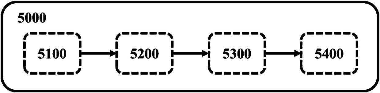
[0030] figure 1 It is a schematic structural diagram of the detection device for carrier envelope phase signals provided by the present invention.

[0031] Such as figure 1 As shown, the device includes a pulse oscillator 5100, an optical fiber amplifier 5200, a spectral stretcher 5300, and a collinear self-reference f-2f carrier envelope phase detection module 5400 that are sequentially connected to the optical path.

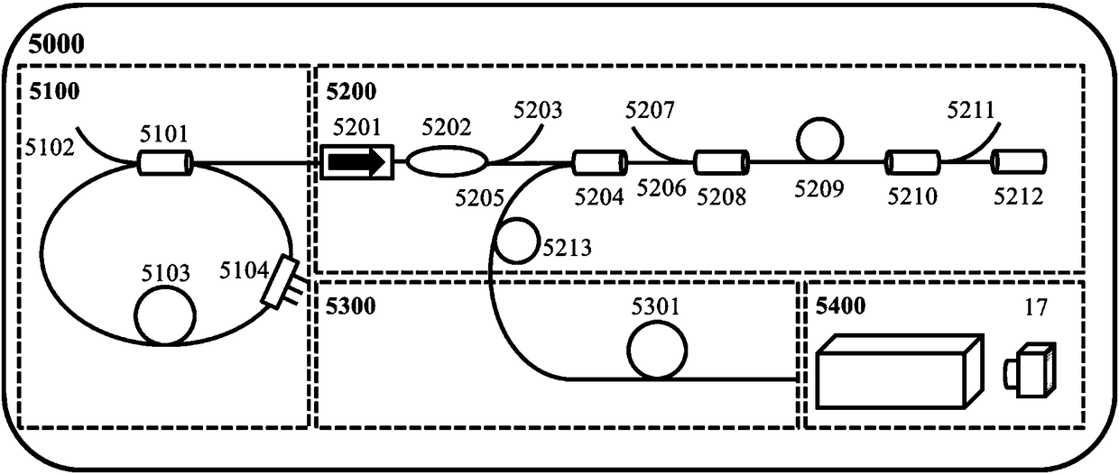
[0032] figure 2 A schematic diagram of the structure of a detection device for a carrier envelope phase signal provided by the embodiment.

[0033] The pulse oscillator 5100 uses an erbium-doped fiber oscillator and a fiber amplifier solution, which can generate femtosecond pulse output near the 1560nm band. The output light of the optical fiber amplifier 5200 is injected into the polarization-maintaining high-nonlinear fiber of the spectral stretcher 5300, and a supercontinuum covering a frequency doubling layer can be obtained at the output end of the polarization-...


PUM


Abstract

The invention provides a detection apparatus of carrier envelope phase signals. The detection apparatus is characterized by comprising a pulse oscillator, a fiber amplifier, a spectrum spread device and a collinear type self-reference f-2f carrier envelope phase detection module which are successively connected through an optical path, wherein the collinear type self-reference f-2f carrier envelope phase detection module comprises multiple lenses, a PPLN crystal, a YV04 crystal and a photoelectric detector which are connected through an optical path, the lens is used for converting fiber light output by the spectrum spread device into space light, the YV04 crystal is used for introducing time-delay amounts of fundamental frequency light and frequency multiplication light, and the YV04 crystal is internally of an oblique cleft structure whose left portion and right portion can be vertically adjusted. Femtosecond pulses are injected into high-nonlinearity fibers for generating needed long-wave signals and short-wave signals, phase delays of long-wave signal pulses and short-wave signal pulses are optimized through polarization dispersion and envelope velocity dispersion of the YV04 crystal, and compared to a method of modifying a time-delay amount by use of space light path adjustment in a conventional apparatus, the accuracy is greatly improved.

Description

Technical field [0001] The invention relates to the technical field of fiber lasers, in particular to a method for detecting the envelope phase of a fiber femtosecond laser carrier, and belongs to the field of photoelectric physics. Background technique [0002] Ultrashort pulse lasers are represented as equally spaced optical frequency columns in the frequency domain, just like the combs people use, so they are called optical frequency combs (optical combs). The rise and development of optical frequency comb technology has provided important help for the research of physical foundation and greatly promoted the development of science. The optical comb is equivalent to an optical frequency integrated generator, which can extend a single frequency optical frequency or microwave frequency to a wide range, and is a powerful tool for scientific research and human life. The optical comb provides a high-resolution, high-precision, high-accuracy frequency standard, which can be widely u...

Claims


Application Information

Patent Timeline
Patent Type & Authority Patents(China)
IPC IPC(8): G01J9/00
CPCG01J9/00
Inventor 郝强刘婷婷曾和平
Owner UNIV OF SHANGHAI FOR SCI & TECH
Why Eureka
Try Eureka