
Machine room cooling system provided with set-top type units

A heat dissipation system, top-mounted technology, applied in air-conditioning systems, household heating, heating methods, etc., can solve the problems of insufficient use of hot air rising, high fan power, long distance of sending and returning air, etc., to save internal space , space-saving and low wind resistance

Inactive Publication Date: 2016-09-28
SHENZHEN ENVICOOL TECH
View PDF14 Cites 3 Cited by
  • Summary
  • Abstract
  • Description
  • Claims
  • Application Information

AI Technical Summary

Problems solved by technology

Although the above two heat dissipation systems solve the problem of the built-in unit occupying the space of the machine room, the cooling scheme of the existing heat dissipation system does not make full use of the favorable airflow organization of hot air rising and cold air falling, resulting in high fan power; and partial cooling In the solution, the distance of sending and returning air is usually long, which will also cause additional wind resistance, resulting in high fan power.

Method used


Image

  • Machine room cooling system provided with set-top type units
  • Machine room cooling system provided with set-top type units
  • Machine room cooling system provided with set-top type units

Examples


Embodiment 1

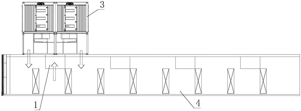
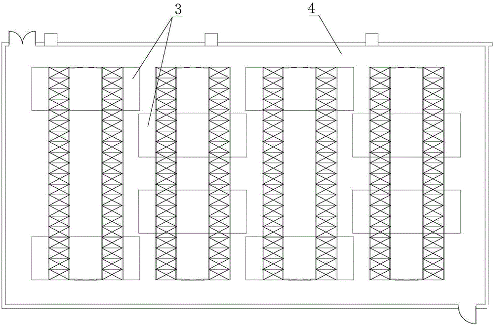
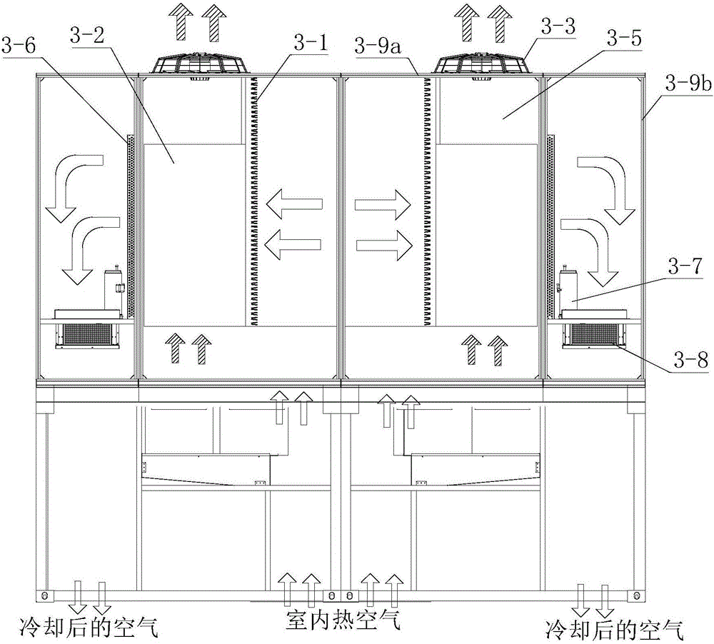
[0028] Such as figure 1 and figure 2 As shown, the heat dissipation system of the computer room in this embodiment includes multiple groups of heat dissipation units 3 arranged outside the top of the computer room 4. For a brief display, figure 1 Only one group of cooling units 3 is shown in the figure. The heat dissipation unit 3 has an air inlet connected to the machine room and an air supply port connected to the machine room. The air inlet and the air supply port are located at the bottom of the heat dissipation unit. The heat dissipation unit 3 also has an outdoor air inlet and an outdoor air outlet connected to the outdoor environment. An outdoor air flow channel is formed in the heat dissipation unit between the outdoor air inlet and the outdoor air outlet, and an indoor air flow channel is formed in the heat dissipation unit between the air inlet and the air supply port, and the outdoor air flow channel and the indoor air flow channel are isolated from each other.

...

Embodiment 2

[0038] Such as Figure 6 As shown, the difference between this embodiment and Embodiment 1 is that this embodiment is a system in which the heat dissipation unit is applied to a closed cold aisle, and Embodiment 1 is a system in which a heat dissipation unit is applied to a closed hot aisle. The indoor air cooled by the heat dissipation unit 3 is discharged into the closed cold aisle 2 from the air outlet at the bottom of the heat dissipation unit 3 . Cooling unit 3 can be arranged left and right ( Figure 4 ), can also be arranged front and back ( Figure 7 ).

[0039] When the closed cold aisle is installed in the computer room, the air cooled by the heat dissipation unit enters the computer room from the air supply port of the heat dissipation unit through the closed cold aisle to cool down the server and other equipment; the hot return air generated by the equipment diffuses into the heat dissipation unit for cooling. Cool down. Similarly, the favorable airflow organiz...

Embodiment 3

[0041] Such as Figure 8 As shown, the difference between this embodiment and Embodiment 1 is that the natural cold source cooling module also includes a spray device 3-4, and the heat exchange and cooling effect is enhanced through the spray device. The spray device 3-4 of this embodiment is set Above the evaporative cooling heat exchanger 3-2, the spraying device 3-4 is connected to the spraying water circulation system (not shown) through a pipeline, and the cooling water is provided by the spraying water circulation system, and the water is sprayed until the evaporation Cooling on heat exchanger 3-2. The spray water circulation system includes a water pump connected by pipes, a water receiving tray and an external supply water source, and the water receiving tray is located below the evaporative cooling heat exchanger 3-2.

[0042] The heat dissipation system of the present invention can be applied to a data machine room with closed hot aisles and / or closed cold aisles. F...


PUM


Abstract

The invention discloses a machine room cooling system provided with set-top type units. The machine room cooling system comprises cooling units which are arranged outside the top of a machine room; each cooling unit comprises a natural cold source cooling module and a mechanical refrigeration module and is provided with an air inlet, air sending openings, an outdoor air inlet and an outdoor air outlet, wherein the air inlet and the air sending openings both communicate with the inside of the machine room; the outdoor air inlet and the outdoor air outlet both communicate with the outdoor environment; indoor air flow passages are formed between the air inlet and the air sending openings inside the cooling unit; an outdoor air flow passage is formed between the outdoor air inlet and the outdoor air outlet inside the cooling unit; the outdoor air flow passage is isolated from the indoor air flow passages; and indoor air and outdoor air are capable of exchanging heat inside the cooling unit. The machine room cooling system disclosed by the invention is capable of fully utilizing the flow trend of cold air flow and hot air flow, and air resistance is small, so energy consumption of a fan is reduced; moreover, the machine room cooling system does not occupy the internal space of the machine room, so rapid parallel-connection extension can be conveniently realized according to refrigeration demands in order to satisfy various refrigeration demands.

Description

technical field [0001] The invention relates to a cooling system for a data machine room, more specifically, to a cooling system for a top-mounted machine room. Background technique [0002] With the high-density integration of IT equipment in the computer room, the phenomenon that the heat dissipation of the equipment is getting higher and higher has attracted strong attention from all walks of life. According to the research, the current related carbon emissions in the IT / telecommunication field have become one of the largest sources of greenhouse gas emissions. According to statistics, the cooling energy consumption of the data center accounts for about 40% of the total power consumption of the computer room. At present, the cooling of the computer room mainly depends on the air conditioner, so reducing the power consumption of the computer room air conditioner is one of the means to effectively reduce the PUE value of the computer room. The PUE (Power Usage Effectivenes...

Claims


Application Information

Patent Timeline
Patent Type & Authority Applications(China)
IPC IPC(8): F24F5/00
CPCF24F5/001F24F5/0035F24F5/0046
Inventor 陈云伟吴刚王铁旺陈川戴向阳吴烨
Owner SHENZHEN ENVICOOL TECH
Learn More